Display panel

A display panel and area technology, applied in the direction of optics, instruments, electrical components, etc., can solve the problems affecting the display effect of the display panel, signal attenuation, etc., and achieve the effect of improving the quality of the picture display

Active Publication Date: 2015-12-02
CENTURY DISPLAY (SHENZHEN) CO LTD
View PDF6 Cites 5 Cited by
  • Summary
  • Abstract
  • Description
  • Claims
  • Application Information

AI Technical Summary

Problems solved by technology

However, the signal will attenuate during transmission, especially in larger-sized display panels, the signal waveform attenuation of the pixel unit farther away from the gate driver is more obvious, which seriously affects the display effect of the display panel

Method used


Image

  • Display panel
  • Display panel
  • Display panel

Examples


Embodiment Construction

[0019] Below in conjunction with accompanying drawing and preferred embodiment the present invention is described in further detail:

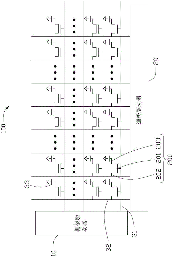
[0020] Please refer to figure 1 , the display panel 100 of the present invention includes a thin film transistor array and a driver of the thin film transistor array, the driver includes a gate driver 10, a source driver 20, and the thin film transistor array includes a plurality of scanning lines 31, a plurality of data lines 32, a plurality of A pixel electrode 33 and a plurality of thin film transistors 200 . The scan lines 31 are connected to the gate driver 10 to transmit scan signals. The data line 32 is connected to the source driver 20 to transmit the data signal generated by the source driver 20 .

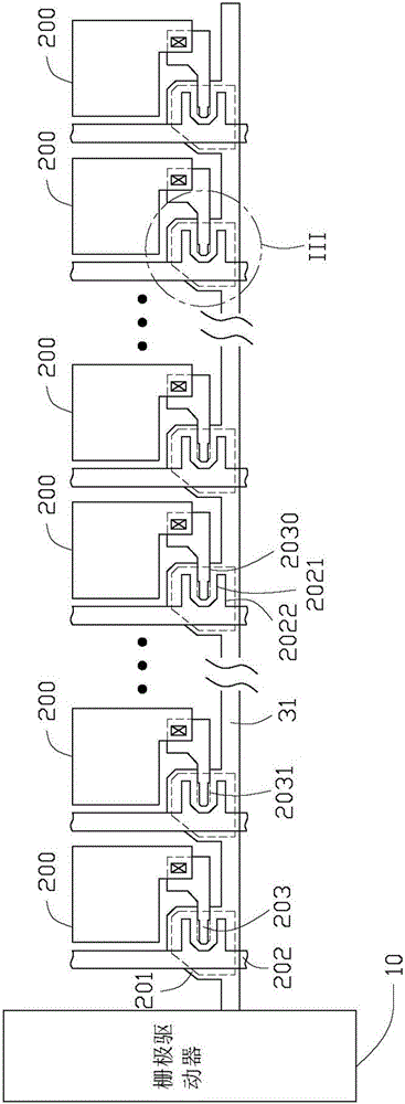
[0021] The TFT 200 includes a gate 201, a source 202 and a drain 203, the gate 201 is connected to the scan line 31, the source 202 is connected to the data line 32, and the drain 203 is connected to the pixel electrode 33 .

[0022] Pl...


PUM


Abstract

The invention provides a display panel. The display panel comprises a grid driver, multiple scanning lines and multiple thin film transistors. The scanning lines are connected with the grid driver, and the thin film transistors are connected to the scanning lines respectively. The grid of each thin film transistor is connected with the corresponding scanning line. The drain electrodes of the thin film transistors are provided with overlapping portions overlapped with the grids in the vertical direction. The area of the overlapping portions in the horizontal direction is evenly and gradually increased from the position close the grid driver to the position far away from the grid driver. According to the display panel, the area of the overlapping portions, overlapped with the grids, of the drain electrodes is changed by changing the area of the drain electrodes of the thin film transistors in the horizontal direction so as to evenly compensate for signal waveforms of pixel units, and accordingly the image display quality of the display panel is improved.

Description

technical field [0001] The invention relates to a display panel, in particular to a liquid crystal display panel. Background technique [0002] With the continuous development of technology and continuous improvement of technology, display panels have been widely used in people's daily life and production, especially liquid crystal display panels, which are widely used in various portable electronic products, transportation tools, etc. [0003] A liquid crystal display panel usually includes a gate driver, a source driver and a pixel unit, and the pixel unit is connected to the gate driver and the source driver through a scan line and a data line respectively. However, the signal will be attenuated during the transmission process, especially in a larger-sized display panel, the signal waveform attenuation of the pixel unit farther away from the gate driver is more obvious, which seriously affects the display effect of the display panel. Contents of the invention [0004] ...

Claims


Application Information

Patent Timeline
Patent Type & Authority Applications(China)
IPC IPC(8): G02F1/1362G02F1/1368
CPCG02F1/136286G02F1/1368H01L27/124H01L29/41733G02F1/13454
Inventor 王明宗柳智忠郑亦秀余文强
Owner CENTURY DISPLAY (SHENZHEN) CO LTD
Why Eureka
Try Eureka