LED display screen matching method

An LED display and screen matching technology, applied in the direction of digital output to display devices, can solve the problems of low use requirements, single application scenarios, high user requirements, etc., and achieve the effect of reducing requirements and reducing the amount of information input

Active Publication Date: 2015-12-02
XIAN NOVASTAR TECH
View PDF6 Cites 43 Cited by
  • Summary
  • Abstract
  • Description
  • Claims
  • Application Information

AI Technical Summary

Problems solved by technology

The software screen matching method can generally cover all types of LED displays. The user directly feeds back all the information of the display to the software, and then the software completes the calculation of the topology information of the LED display in the background. The whole process has

Method used


Image

  • LED display screen matching method
  • LED display screen matching method
  • LED display screen matching method

Examples


no. 1 example

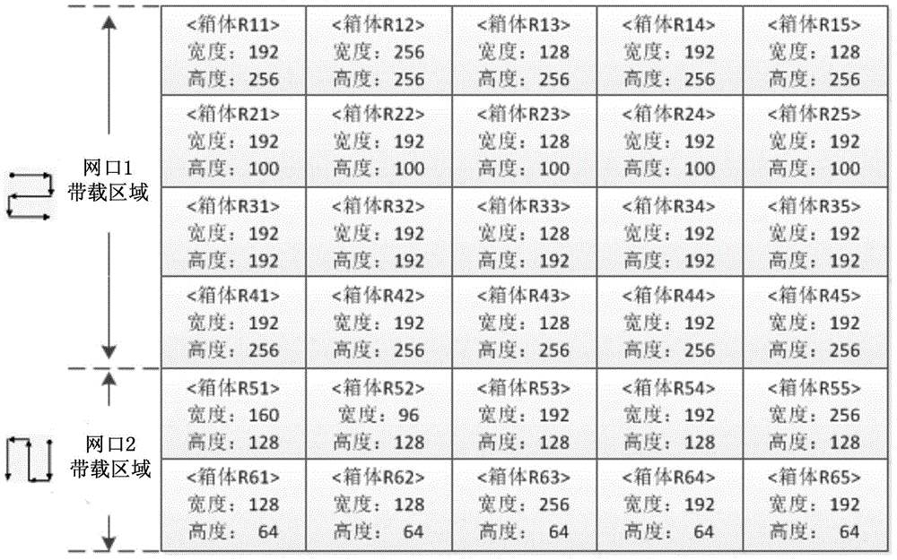
[0020] The first embodiment of the present invention proposes a LED display screen matching method based on screen matching software. In order to facilitate the understanding of this embodiment, the figure 1 The LED display shown is taken as an example for explanation.

[0021] Such as figure 1 As shown, the LED display screen includes 5 columns and 6 rows, a total of 30 splicing units, such as 30 cabinets. The width and height of these cabinets (in terms of pixels) include 192*256, 256*256, 128*256 . Complex screens with different heights and sizes are loaded by the two network ports of the sending card. Network port 1 carries 5 columns and 4 rows, network port 2 carries 5 columns and 2 rows, network port 1 is the upper left horizontal serial line, network port 2 is the upper right vertical string, the width and height of each box (that is, the width and height of the loading area corresponding to the receiving card) are as follows figure 1 Show. It is worth mentioning th...

no. 2 example

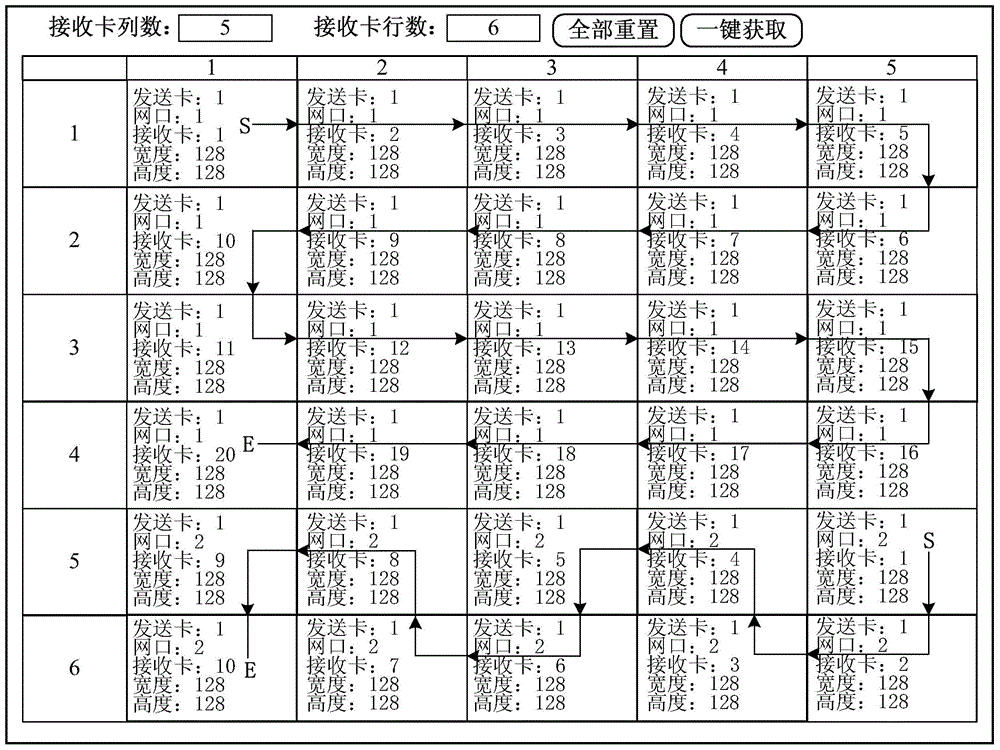
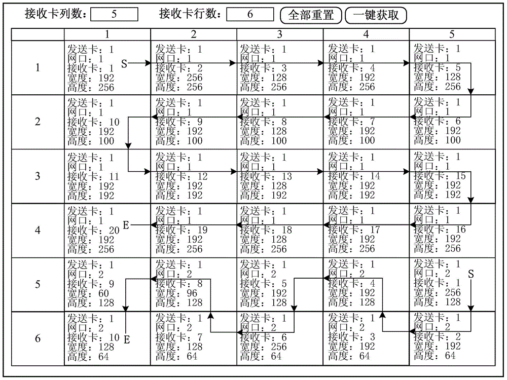
[0031]The second embodiment of the present invention proposes a hardware-based LED display screen configuration method. The user only needs to input the parameter values ​​in the following table on the LCD interface supported by the sending card in the LED display control system:

[0032]

[0033] In the above table, the parameter values ​​set are the same as figure 1 The topological information of the LED display shown is consistent, and the parameter value "804" of the row coordinates of the starting pixel point of the loading area of ​​the network port 2 is the height of each cabinet loaded by the network port 1 in the row direction by summing up obtained, and each parameter value in the table can be input through the knob or key.

[0034] Based on the above, after the user completes the input of the parameter values ​​in the above table, the sending card will know the number of loaded rows and columns and the routing mode of each network port of the sending card in the ...


PUM


Abstract

The invention relates to an LED display screen matching method, which is suitable for not only software screen matching but also hardware screen matching. User input and intelligent acquisition from hardware are combined and cooperate for finishing acquisition of topological information of an LED display screen, so that information input quantity of a user can be reduced and the user only needs to provide simple information of row and column numbers of case bodies, a routing mode and the like of the LED display screen; and actual loaded information of a receiving card corresponding to each case body is acquired by accessing to the hardware, so that the user requirements are lowered.

Description

technical field [0001] The present invention relates to the technical field of display control, and in particular relates to a method for distributing LED display screens. Background technique [0002] With the development of LED technology, more and more LED display screens appear in people's field of vision in various forms, similar to special-shaped screens with unique shapes such as spherical screens, general regular display screens may also be composed of various shapes, The emergence of these application scenarios, on the one hand, makes the LED display system have a wider application space, and on the other hand, it also puts forward higher requirements for the control of the LED display. In order to realize the control of the LED display, completely and accurately describing the topology information of the LED display is the key first step, and it is also an important part of the entire LED display control operation, and its difficulty directly affects the customer e...

Claims


Application Information

Patent Timeline
IPC IPC(8): G06F3/14
Inventor 周晶晶王红宾王伙荣
Owner XIAN NOVASTAR TECH
Why Eureka
Try Eureka