
Die assembly of pull-in coil inserting machine

A wire-embedding machine and component technology, applied in electric components, electrical components, electromechanical devices, etc., to achieve the effect of wide application range and simple structure

Active Publication Date: 2015-12-02
圣玛特智能设备制造(浙江)有限公司
View PDF6 Cites 0 Cited by
  • Summary
  • Abstract
  • Description
  • Claims
  • Application Information

AI Technical Summary

Problems solved by technology

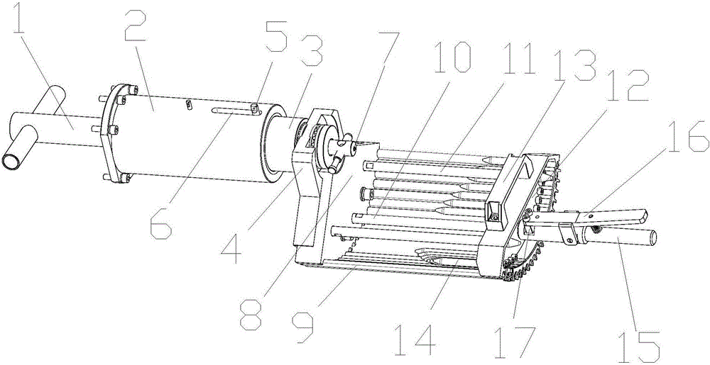
When it is necessary to process different types of stators, the mold assembly needs to be reset according to the size and model of the stator. The mold assembly of the existing pull-in wire inserting machine can only be applied to a single type of stator

Method used


Image

  • Die assembly of pull-in coil inserting machine
  • Die assembly of pull-in coil inserting machine

Examples


Embodiment Construction

[0012] The preferred embodiments of the present invention will be described in detail below in conjunction with the accompanying drawings, so that the advantages and features of the present invention can be more easily understood by those skilled in the art, so as to define the protection scope of the present invention more clearly.

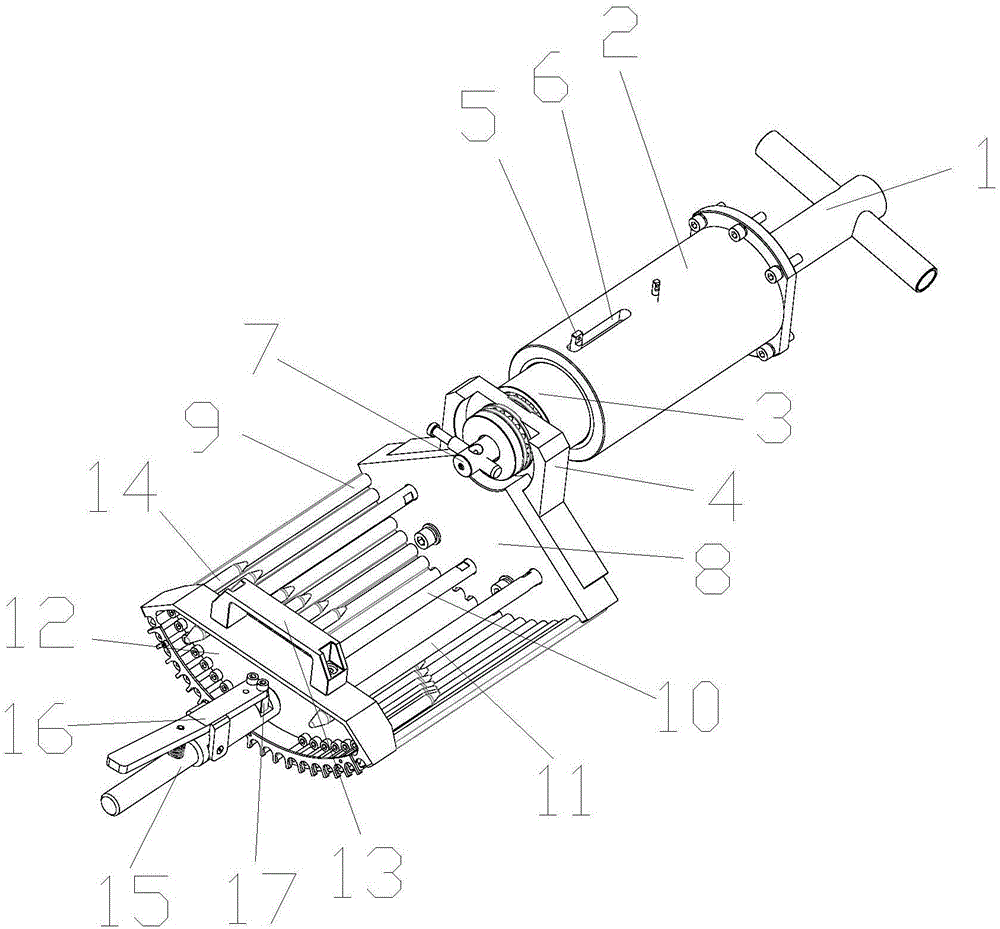
[0013] see figure 1 and figure 2 , the embodiment of the present invention includes:

[0014] A mold assembly of a pull-in wire embedding machine, including: a small round nut wrench 1, a guide assembly, a wire cup assembly and a quick locking assembly; the guide assembly includes a guide assembly fixing seat 2, a tension support seat 4, a guide bar Mounting seat 8, guide connecting shaft 3, round nut, spring screw 5, locking shaft 7, locking pin, pull rod 10, guide strip 9 and guide rod 11; the small round nut wrench 1 is fixed on the pull wire of the wire inserting machine Mechanismally, the guide assembly fixing seat 2 is provided with a co...


PUM


Abstract

The invention discloses a die assembly of a pull-in coil inserting machine. The die assembly comprises a small circular nut wrench and a guiding assembly. The guiding assembly comprises a guiding assembly fixing seat, a pulling force support seat, a guiding connection shaft, a circular nut, a spring screw, and a locking shaft. The guiding assembly fixing seat is equipped with a connection shaft limiting groove. One end of the guiding connection shaft is disposed in the guiding assembly fixing seat. The other end of the guiding connection shaft is disposed on the pulling force support seat. The spring screw passes through the connection shaft limiting groove and is fixed to the guiding connection shaft. The circular nut is fixed to the end portion, in the guiding assembly fixing seat, of the guiding connection shaft. The small circular nut wrench is meshed with the circular nut. The locking shaft is fixed to the end portion, located at the pulling force support seat, of the guiding connection shaft. The locking shaft is connected with the guiding connection shaft. By means of the above manner, the die assembly is suitable for the wire-pulling processes of stators in various models, capable of easily and fast pulling wires, simple in structure, and wide in application range.

Description

technical field [0001] The invention relates to the field of wire embedding machine tooling, in particular to a pull-in wire embedding machine mold assembly. Background technique [0002] The mold assembly of the pull-in wire embedding machine is used for the wire drawing process of the stator to be processed, so that the stator can be positioned quickly and the wire embedding processing of the stator is convenient. When it is necessary to process different types of stators, the mold assembly needs to be reset according to the size and model of the stator. The mold assembly of the existing pull-in wire inserting machine can only be applied to a single type of stator. Contents of the invention [0003] The main technical problem to be solved by the present invention is to provide a pull-in type wire embedding machine mold assembly, which can be used in the wire drawing process of various types of stators when used in the wire drawing mechanism, and can complete the wire dra...

Claims


Application Information

Patent Timeline
Patent Type & Authority Applications(China)
IPC IPC(8): H02K15/085
Inventor 王建
Owner 圣玛特智能设备制造(浙江)有限公司
Learn More