Nematic liquid crystal composition, and liquid crystal display element incorporating same

A liquid crystal composition and compound technology, applied in liquid crystal materials, chemical instruments and methods, instruments, etc., can solve problems such as poor display, slow response speed, and reduction of VA-type display elements, and achieve excellent display quality and fast response speed Effect

Active Publication Date: 2015-12-02
DIC CORP
View PDF18 Cites 18 Cited by
  • Summary
  • Abstract
  • Description
  • Claims
  • Application Information

AI Technical Summary

Problems solved by technology

[0019] In this way, attempts are being made to solve the problem of poor display accompanying the alignment of liquid crystal molecules in PSA display elements having useful display properties (contrast, response speed) by optimizing polymeric compounds. On the other hand, depending on the composition of PSA display elements The components of the liquid crystal composition, there are components that are not suitable for PSA display elements
In particular, a liquid crystal composition containing a liquid crystal material having an alkenyl group effective for lowering the viscosity is effective for reducing the response speed of a VA-type display element, but there is a new problem related to orientation control: when used as a PSA-type display After polymerizing the polymerizable compound in the device manufacturing process, it hinders the pretilt angle of the liquid crystal molecules
When an appropriate pre-tilt angle cannot be given to the liquid crystal molecules, the movement direction of the liquid crystal molecules during driving cannot be specified, and the liquid crystal molecules will not tilt in a certain direction, causing problems such as lower contrast or slower response speed.
[0020] In addition, Patent Document 6 discloses that the response speed of the vertical liquid crystal cell can be improved by using a liquid crystal material with a large index shown in (Formula 1), but it cannot be said to be sufficient.

Method used


Image

  • Nematic liquid crystal composition, and liquid crystal display element incorporating same
  • Nematic liquid crystal composition, and liquid crystal display element incorporating same
  • Nematic liquid crystal composition, and liquid crystal display element incorporating same

Examples


Embodiment

[0222] Hereinafter, examples are given and the present invention will be described in further detail, but the present invention is not limited to these examples. In addition, "%" in the composition of a following Example and a comparative example means "mass %".

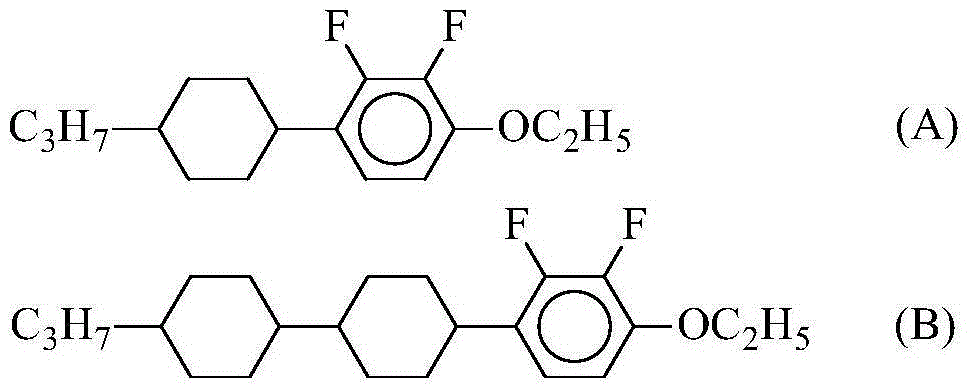
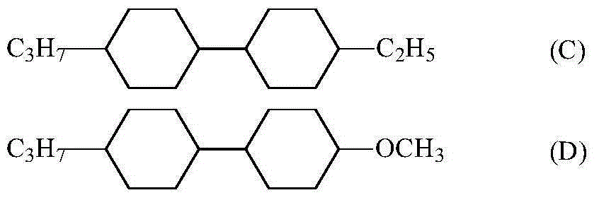
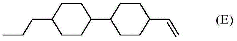
[0223] The following abbreviations are used to describe the compounds in the Examples.

[0224] (side chain)

[0225] -n-C n h 2n+1 straight-chain alkyl group with n carbon atoms

[0226] n-C n h 2n+1 - straight-chain alkyl group with n carbon atoms

[0227] -On-OC n h 2n+1 straight-chain alkoxy group with n carbon atoms

[0228] nO-C n h 2n+1 O- straight-chain alkoxy group with n carbon atoms

[0229] -V-CH=CH 2

[0230] V-CH 2 =CH-

[0231] -V1-CH=CH-CH 3

[0232] 1V-CH 3 -CH=CH-

[0233] -2V-CH 2 -CH 2 -CH=CH 3

[0234] V2-CH 3 =CH-CH 2 -CH 2 -

[0235] -2V1-CH 2 -CH 2 -CH=CH-CH 3

[0236] 1V2-CH 3 -CH=CH-CH 2 -CH 2

[0237] (ring structure)

[0238] [chem 42]

[0239]

[0...

Embodiment 3~ Embodiment 6

[0261] In order to confirm the difference in tendency caused by the composition system, LC-3 (Example 3), LC-4 (Example 4), LC-5 (Example 5) and LC-6 (Example 6) containing polymerization The liquid crystal composition of the active compound was measured for its physical property value. Table 2 shows the composition of the liquid crystal composition containing the polymerizable compound and the results of its physical properties.

[0262][Table 2]

[0263]

[0264] These liquid crystal compositions containing a polymerizable compound were injected into a cell with ITO coated with a polyimide alignment film for inducing vertical alignment and subjected to a rubbing treatment with a cell gap of 3.5 μm by a vacuum injection method. Apply a 5.0V square wave, and adjust the irradiation intensity on the surface of the unit to 100mW / cm using a high-pressure mercury lamp through a filter that filters out ultraviolet rays below 320nm 2 And UV irradiation was performed, and the ver...

Embodiment 7~ Embodiment 12

[0269] In order to confirm the difference in tendency due to the type of monomer, LC-7 (Example 7) and LC-8 in which various monomers were added were prepared by setting the host liquid crystal (host liquid crystal) used in Example 2 as LCX. (Example 8), LC-9 (Example 9), LC-10 (Example 10), LC-11 (Example 11) and LC-12 (Example 12) liquid crystal compositions containing polymerizable compounds , to measure its physical properties. Table 3 shows the composition of the liquid crystal composition containing the polymerizable compound and the results of its physical properties.

[0270] [table 3]

[0271]

[0272] These liquid crystal compositions containing a polymerizable compound were injected into a cell with ITO coated with a polyimide alignment film for inducing vertical alignment and subjected to a rubbing treatment with a cell gap of 3.5 μm by a vacuum injection method. Apply a 5.0V square wave, and adjust the irradiation intensity on the surface of the unit to 100mW...


PUM

PropertyMeasurementUnit
viscosityaaaaaaaaaa
thicknessaaaaaaaaaa
refractive indexaaaaaaaaaa

Abstract

 The present invention pertains to a nematic liquid crystal composition having negative dielectric anisotropy (Δε), containing a polymerizable compound, and useful as a liquid crystal display material, and pertains to a liquid crystal display element in which the nematic liquid crystal composition is used. This liquid crystal composition is obtained by polymerizing a polymerizable compound without inhibiting the formation of a pretilt angle in liquid crystal molecules by irradiation with ultraviolet rays in order to produce an element, and can provide a fast-response PSA-type display element in which the pretilt angle is adequately imparted thereby, satisfactory orientation stability is obtained, display defects are absent or inhibited, and high display quality is obtained. A liquid crystal display element in which this liquid crystal composition is used can serve as a liquid crystal display element for active matrix driving, and can be applied to PSVA-mode liquid crystal display elements.

Description

technical field [0001] The present invention relates to a nematic liquid crystal composition having a negative dielectric constant anisotropy (Δε) useful as a liquid crystal display material, and a liquid crystal display element using the same. Background technique [0002] Liquid crystal display devices are used in various household electrical appliances including clocks and calculators, measuring equipment, automotive panels, word processors, electronic notebooks, printers, computers, and televisions. Representative examples of liquid crystal display methods include TN (twisted nematic) type, STN (super twisted nematic) type, DS (dynamic light scattering) type, GH (guest-host) type, IPS (in-plane switching) type, and OCB type. (Optically Compensated Birefringence) type, ECB (Voltage Controlled Birefringence) type, VA (Vertical Alignment) type, CSH (Color Super Vertical) type or FLC (Ferroelectric Liquid Crystal) and the like. Further, examples of the driving method includ...

Claims


Application Information

Patent Timeline
Patent Type & Authority Applications(China)
IPC IPC(8): C09K19/30C09K19/12C09K19/14C09K19/18C09K19/20C09K19/24C09K19/32C09K19/34C09K19/38C09K19/54G02F1/13
CPCC09K19/322C09K19/2014C09K19/3066C09K19/54C09K2019/0448C09K2019/122C09K2019/123C09K2019/3004C09K2019/3009C09K2019/301C09K2019/3027C09K2019/3037C09K2019/548G02F1/133788G02F2001/133742G02F2001/13712G02F1/133742G02F1/13712C09K19/56
Inventor 平田真一栗山毅川上正太郎
Owner DIC CORP
Why Eureka
Try Eureka