Methods and apparatuses for characterization of single polymers

a single polymer and characterization technology, applied in the field of single polymer characterization methods and apparatuses, can solve the problems of reducing the amount of sample material generated, and avoiding tedious efforts in generating large amounts of sample material, so as to reduce the channel depth

Inactive Publication Date: 2004-07-13
U S GENOMICS INC
View PDF22 Cites 145 Cited by
  • Summary
  • Abstract
  • Description
  • Claims
  • Application Information

AI Technical Summary

Problems solved by technology

Single-molecule analytical methods require small amounts of sample, thereby alleviating tedious efforts in generating large amounts of sample material.
The method does not provide information regarding the internal structure of a molecule.
Thus, the method does not use electrophoretic mobilities to determine sizes of molecules.
This method also does not provide information regarding the internal structure of a molecule.
The disadvantage of this method is that, in order to design probes of the proper sequence, the exact sequence of the target nucleic acid and surrounding sequences must be known.
None of these single molecule analytical methods allows the determination of the internal structure of the molecule.
A challenge to the characterization of the internal structure, e.g., the linear sequence of monomers, in a single polymer chain is from the natural tendency of polymers in most media to adopt coiled conformations.
However, no data were given to determine the quality of the stretching of large polymers, and the technique is limited to analyzing approximately 3 megabases at a time.
The DNA was then immobilized on the slide, making processing, e.g., fluorescent labeling, prior to stretching relatively difficult.
The method, which does not provide means for determining the velocity of the DNA molecule, relies on estimating the velocity of DNA from the migration rate of the DNA molecule.
Flow based single-molecule analytical methods for elongation and characterization of single macromolecules have not been widely adopted due in part to the difficulty in precise measurement of molecular characteristics, e.g., the length of the macromolecule, the distance between two landmarks on a macromolecule, etc.

Method used


Image

  • Methods and apparatuses for characterization of single polymers
  • Methods and apparatuses for characterization of single polymers
  • Methods and apparatuses for characterization of single polymers

Examples


example 1

6.1 EXAMPLE 1

Fabrication of a Chip For Stretching DNA and its use in an Apparatus for Detecting Fluorescene Emission From Labeled DNA

Experimental Apparatus

A sensitive optical apparatus for detection is shown in FIG. 25. The apparatus utilizes confocal fluorescence illumination and detection. Confocal illumination allows a small optical volume (of the order of femtoliters) to be illuminated. Both Rayleigh and Raman scattering are minimized using a small probe volume. The beam from a 1 mW argon ion laser is passed through a laser line filter (514 nm), directed to a dichroic mirror, through a 100.times.1.2 NA oil immersion objective, and to the sample. The fluorescent tag on the DNA can be one of several dyes including Cy-3, tetramethylrhodamine, rhodamine 6G, and Alexa 546. In addition, intercalator dyes can be used such as TOTO-3 (Molecular Probes). The fluorescence emission from the sample is passed through a dichroic, a narrow bandpass (e.g. Omega Optical), focused onto a 100 .mu.m...

example 2

6.2 Example 2

Stretching of Phage Lambda DNA Using Apparatuses of the Invention

Two different apparatuses were used to obtain the data shown in FIG. 31(a) and 31 (b). The apparatus shown in FIG. 21 was used to obtain the data shown in FIG. 30(b). The apparatus used to obtain the data in FIG. 31(a) had the same channel boundaries as the apparatus used to obtain the data shown in FIG. 31(b) (i.e., the ratio of the sizes of the two tapered regions of the two-funnel apparatus were identical), except that there were no posts present in the structure.

A fused silica wafer (Hoya Corp., San Jose, Calif.) was etched with the pattern in FIG. 21 by a contractor using photolithographic methods described above. The wafer was diced into 1 cm by 2 cm chips using a dicing saw (e.g. from Disco Corp., Santa Clara, Calif.), and a fused silica cover slip (e.g. from Esco, Oak Ridge, N.J.) was attached by thermal bonding.

Double stranded lambda DNA (Promega, Madison, Wis.) having a uniform length of 48.5 kil...

example 3

6.3 Example 3

Stretching of Phage Lambda DNA Using Apparatuses of the Invention

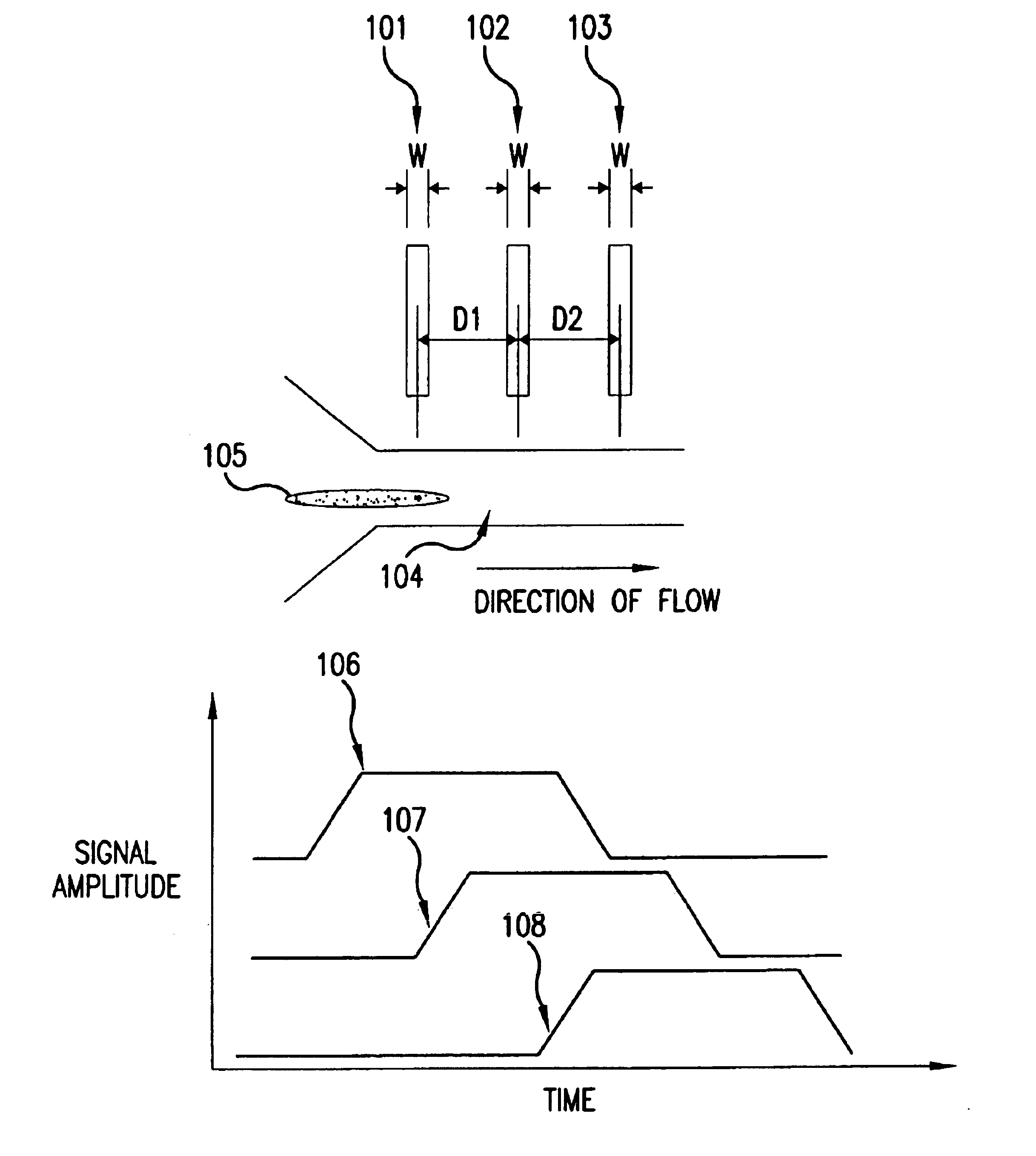
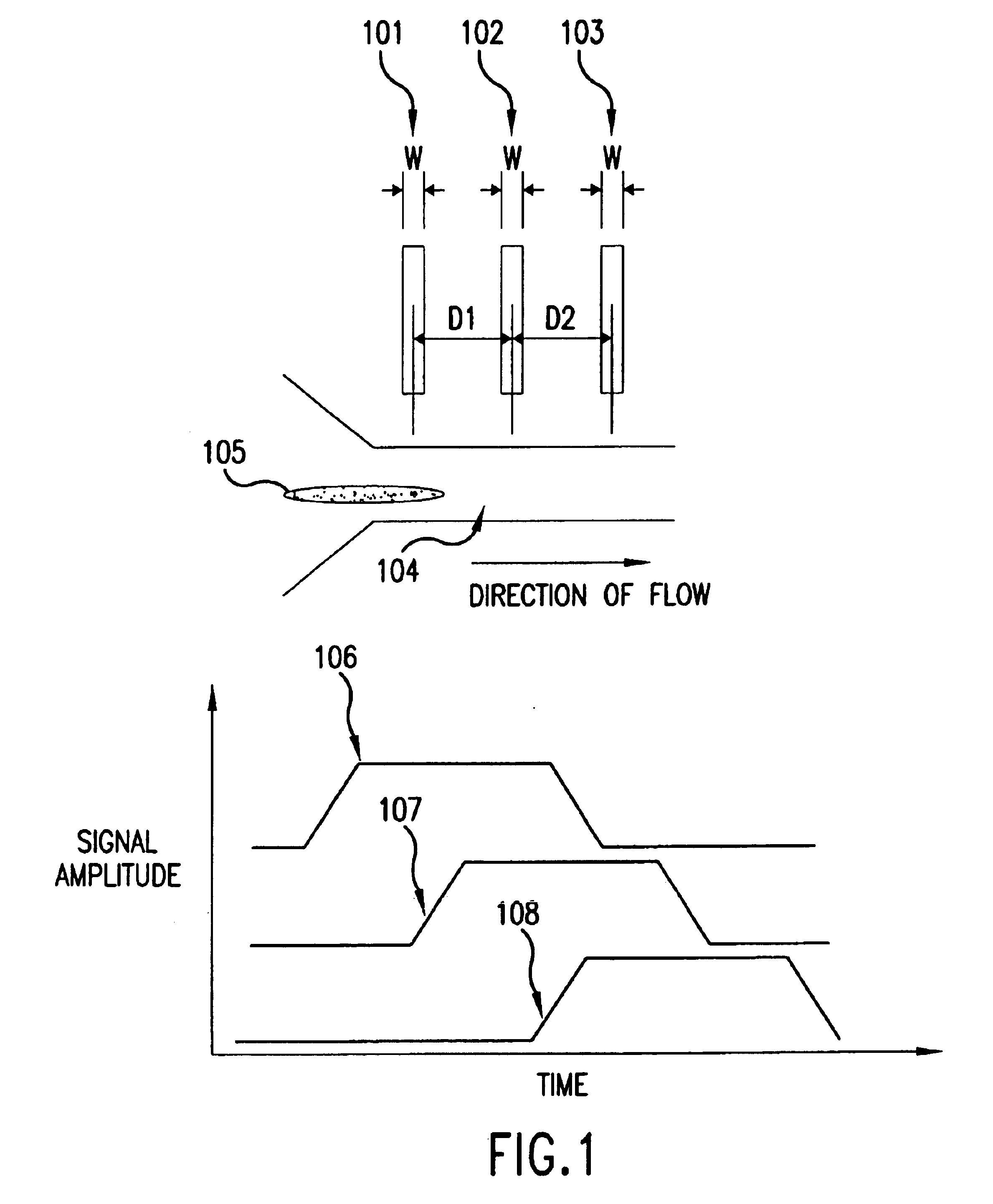
The data shown in FIGS. 37-39 were derived from a dual laser spot arrangement as illustrated in FIG. 36. The DNA was driven through a quartz chip with etched nanochannel of the following design: The depth of the quartz chip is 300 nm. The chip was fabricated using electron beam lithography that involved a series of steps known in the art, which include coating the quartz wafer with a resist, exposing the required areas using a resist using the electron beam, stripping the exposed resist, and etching using reactive ion etch to give straight wall profiles, and finally removing the resist. The laser used to excite dye molecules was a argon ion laser running at 488 nm. The laser delivers about 2 mW of laser power to each of the spots. The spots were diffraction limited, with a spot size of approximately 0.5 microns in diameter. The laser spots were separated 15 .mu.m apart and located along the direction of th...


PUM

PropertyMeasurementUnit
diameteraaaaaaaaaa
diameteraaaaaaaaaa
lengthsaaaaaaaaaa

Abstract

The present invention relates to methods and apparatuses for characterization of single polymers. In particular, the invention relates to methods and apparatuses for determination of the velocities of single elongated polymers. Center-of-mass velocity, center-to-center velocity, end-to-end velocity and rise-time velocity are determined using time-correlated measurements of single elongated polymers in two or more detection zones. The invention also relates to methods of determinating lengths and molecular masses of single polymers and to methods of determining the distance between landmarks on a single polymers based on their velocities. The invention further relates to methods of single-molecule DNA restriction fragment analysis.

Description

1. FIELD OF THE INVENTIONThe present invention relates to methods and apparatuses for characterization of single polymers. In particular, the invention relates to methods and apparatuses for determination of the velocities of single elongated polymers. The invention also relates to methods for determination of the length and molecular mass of single polymers. The invention further relates to methods of determining the distance between landmarks on single polymers.2. BACKGROUND OF THE INVENTIONAnalysis of the structure and dynamics of single macromolecules in a fluid sample has attracted considerable interest due in part to the rapid development of methodologies for the manipulation and detection of single macromolecules. For example, recent developments in experimental techniques and available hardware have increased dramatically the sensitivity of detection so that optical detection can be made of single dye molecules in a sample. Single dye detection can be done in aqueous solutio...

Claims


Application Information

Patent Timeline
Patent Type & Authority Patents(United States)
IPC IPC(8): B01L3/00B01F13/00B01F5/06G01N15/14G01N1/28C12Q1/68G01N33/44
CPCB01F5/061B01F5/0646B01F13/0059B01L3/502746B01L3/502761G01N1/286G01N15/1456B01F5/064Y10T436/143333B01L3/50273B01L2200/0647B01L2200/0663B01L2300/0816B01L2400/086C12Q1/6869G01N15/1459G01N33/442G01N2015/1493G01N2015/1495B01F25/431B01F25/432B01F25/433B01F33/30
Inventor CHAN, EUGENE Y.GLEICH, LANCE C.WELLMAN, PARRIS S.
Owner U S GENOMICS INC
Why Eureka
Try Eureka