Compound, liquid crystal composition, and anisotropic material

a technology of liquid crystal composition and anisotropic material, which is applied in the direction of liquid crystal compositions, organic chemistry, chemistry apparatus and processes, etc., can solve the problems of not being satisfied in the characteristics of wide-band /4 wave plates using liquid crystal compositions, and achieve and improve the reverse wavelength dispersion characteristics of n

Inactive Publication Date: 2009-07-30
FUJIFILM CORP
View PDF0 Cites 194 Cited by
  • Summary
  • Abstract
  • Description
  • Claims
  • Application Information

AI Technical Summary

Benefits of technology

[0008]It is therefore an object of the present invention to provide a novel compound exhibiting reversed wavelength dispersion characteristics of Δn, and improved in reversed wavelength dispersion characteristics of Δn particularly in longer wavelength region; a liquid crystal composition containing the compound; and an optically anisotropic material using the liquid crystal composition.

Problems solved by technology

The conventional retardation plates are capable of adjusting retardation of monochromatic light to ¼ or ½ of the wavelength thereof, but a problem arises in that white light, which is a synthetic light having rays in the visible region mixed therein, may be converted only into a colored polarized light, due to distribution of the state of polarization at the individual wavelength.
The conventional wide-band λ / 4 wave plate using a liquid crystal composition having reversed wavelength dispersion characteristics of retardation is, however, not so satisfactory in the characteristics particularly in the longer wavelength region, and has been remained to be further improved.

Method used


Image

  • Compound, liquid crystal composition, and anisotropic material
  • Compound, liquid crystal composition, and anisotropic material
  • Compound, liquid crystal composition, and anisotropic material

Examples


example 1

Exemplary Synthesis of Exemplary Compound (I-2)

[0136]Exemplary compound (I-2) was synthesized according to a route shown below.

Synthesis of Compound (I-2)-B:

[0137]Using benzoquinone (compound (I-2)-A) as a starting material, compound (I-2)-B was obtained according to the method described in J. Org. Chem., 69, p. 2164-2177 (2004).

Synthesis of Compound (I-2)-C:

[0138]Added were 4.2 g (12.8 mmol) of compound (I-2)-B and 2.9 g (12.5 mmol) of ethyl 1-phenyl-2-pyrazoline-5-on-3-carboxylate to 50 mL of N-methyl-pyrrolidinone, and the mixture was stirred at 95° C. for 2 hours. The mixture was cooled to room temperature, added with 100 mL of ethyl acetate and 100 mL of water for extraction, the organic layer was washed with 100 mL of dilute hydrochloric acid, then washed with 100 mL of water, and dried over sodium sulfate. The obtained organic layer was condensed, and purified by silica gel column chromatography (ethyl acetate was used as an eluent), to obtain 3.2 g of the target compound (I...

example 2

[0152]Compounds (I-1), (I-3) to (I-5), (I-11), (I-13), and (I-16) were respectively synthesized by replacing, (I-2)-I in the synthetic route in Example 1, with any of correspondent I-Substance, and replacing (I-2)-C with any of correspondent C-Substance listed below.

I-SubstanceC-Substance

example 3

Measurement of Absorbance of Solution

[0153]Five milligrams of compound (I-2) was dissolved into 250 mL of chloroform, and absorption spectrum over the UV to visible regions was measured. λmax was observed at 427 nm, with a molar absorption coefficient of 2×10⁴.


PUM

PropertyMeasurementUnit
wavelengthaaaaaaaaaa
wavelengthsaaaaaaaaaa

Abstract

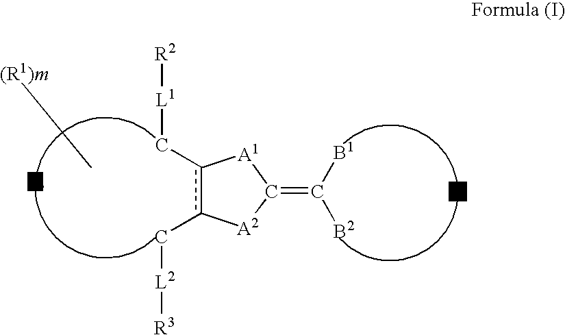
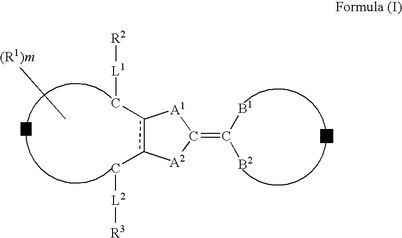
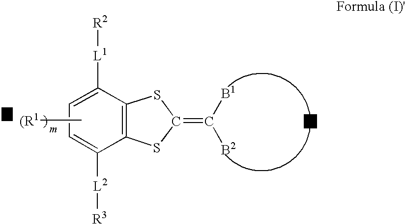
A compound represented by formula (I) below:
    • where, each of A1 and A2 independently represents a group selected from the group consisting of —O—, —NR— (R represents a hydrogen atom or substituent), —S— and —CO—; Z forms a five- or six-membered ring together with C—C═C—C or C═C—C═C illustrated in the formula; Y forms a five- to seven-membered ring together with B1—C—B2 illustrated in the formula, provided that those having the same substituent for A1 and B1 and for A2 and B2 and those having the same substituent for A1 and B2 and for A2 and B1 are excluded, is disclosed.

Description

CROSS-REFERENCE TO RELATED APPLICATIONS[0001]This application claims benefit of priority under 35 U.S.C. 119 to Japanese Patent Application No. 2008-017125 filed on Jan. 29, 2008, which is expressly incorporated herein by reference in its entirety.BACKGROUND OF THE INVENTION[0002]1. Field of the Invention[0003]The present invention relates to a novel compound, a liquid crystal composition containing the same, and an anisotropic material obtained by fixing alignment of the liquid crystal composition.[0004]2. Related Art[0005]So-called retardation plates publicly known include thin plates composed of an inorganic material such as calcite, mica, quartz or the like, and stretched polymer films having large intrinsic birefringence. The retardation plates may be categorized into ¼ wave plate (abbreviated as “λ / 4 plate”, hereinafter) converting linear polarization into circular polarization, and ½ wave plate (abbreviated as “λ / 2 plate”, hereinafter) causing 90° conversion of the plane of p...

Claims


Application Information

Patent Timeline
Patent Type & Authority Applications(United States)
IPC IPC(8): C09K19/34C07D409/04C07D333/52
CPCC07D409/04C07D417/04C09K19/32C09K19/3405C09K19/3477C09K2019/3408C09K19/3483C09K19/3486C09K19/3491C09K19/3497C09K19/348
Inventor TAKEUCHI, HIROSHI
Owner FUJIFILM CORP
Why Eureka
Try Eureka