
Helical reinforcement bending equipment

A spiral steel bar bending technology, applied in the field of spiral steel bar bending equipment, can solve problems such as low operating efficiency, high labor intensity, and troublesome reinforcement cage binding, and achieve the effects of saving labor, saving consumption, and accelerating bending efficiency

Active Publication Date: 2015-12-09
POWERCHINA MUNICIPAL CONSTR GRP CO LTD
View PDF6 Cites 0 Cited by
  • Summary
  • Abstract
  • Description
  • Claims
  • Application Information

AI Technical Summary

Problems solved by technology

The above-mentioned method of bending and forming hoops has the disadvantages of high labor intensity and low operating efficiency. In addition, the subsequent binding of the reinforcement cages is also troublesome and time-consuming, and when binding the reinforcement cages, two hoops per circle A certain amount of overlap needs to be reserved between the ends, resulting in waste of materials

Method used


Image

  • Helical reinforcement bending equipment
  • Helical reinforcement bending equipment
  • Helical reinforcement bending equipment

Examples


Embodiment Construction

[0022] In order to further understand the invention content, characteristics and effects of the present invention, the following examples are given, and detailed descriptions are as follows in conjunction with the accompanying drawings:

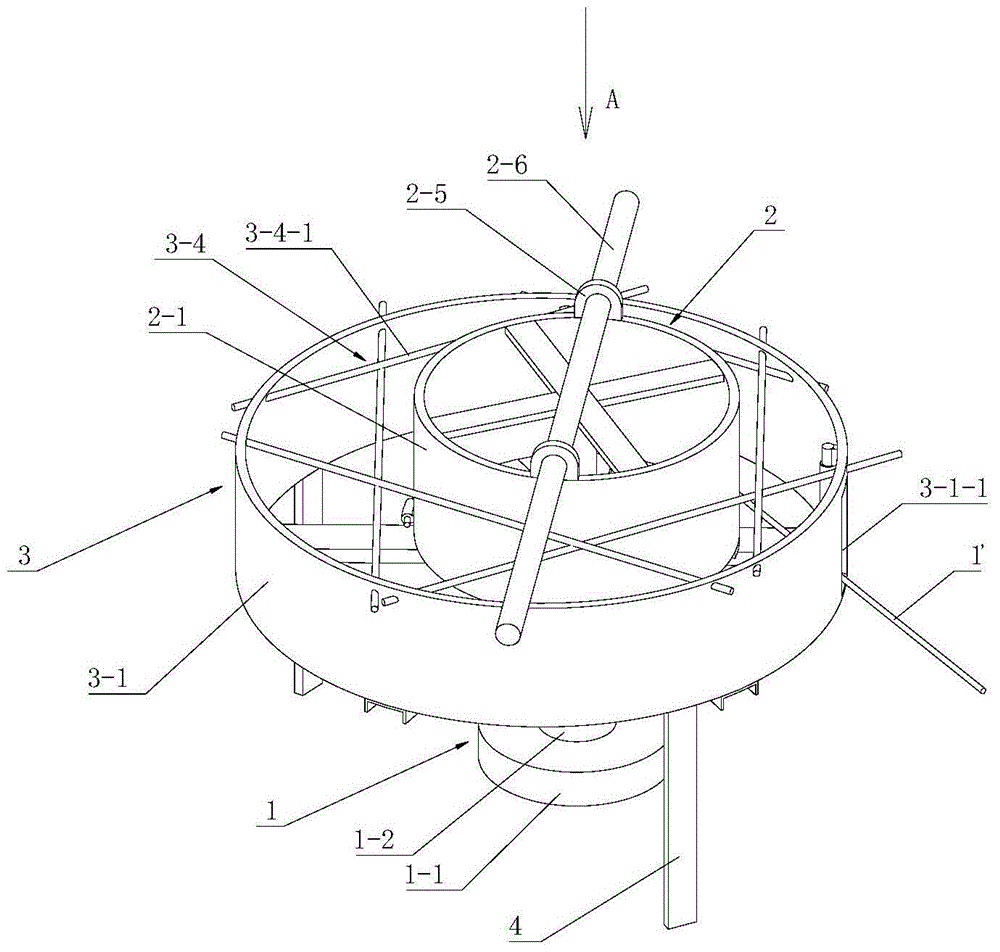
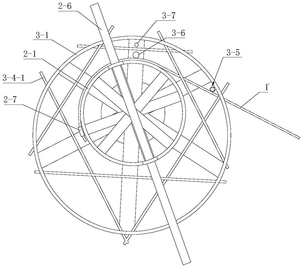
[0023] see Figure 1-5 , a spiral steel bar bending equipment is composed of a base frame part 1, a bending execution part 2 and a formed steel bar storage part 3.

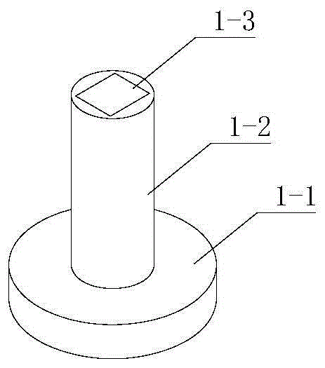
[0024] The pedestal part includes a base 1-1 and a column 1-2 fixedly supported on the base.

[0025] The bending execution part includes a rotating drum 2-1, and a rotating sleeve 2-2 is arranged at the center of the rotating drum. The bracket 2-4 is connected with the rotating drum, and two lugs 2-5 with sockets are arranged on the top of the rotating drum, and a push bar 2-6 is inserted in the two lugs, and the outer wall of the rotating drum An end fixing structure 2-7 for fixing the ends of the reinforcing bars is provided on the top.

[0026] The forming storage part is ...


PUM


Abstract

The invention discloses helical reinforcement bending equipment which consists of a base frame part, a bending actuation part and a formed reinforcement collecting part, wherein the base frame part comprises a base and a vertical column; the bending actuation part comprises a rotary drum, a rotating sleeve and a top frame and a bracket which are used for connecting the rotary drum with the rotating sleeve; two lugs are arranged at the top of the rotary drum; push levers are plugged into the two lugs; an end part fixing structure for fixing the end part of a reinforcement is arranged on the outer side wall of the rotary drum; the formed reinforcement collecting part consists of a coaming, a bottom rack, a supporting shaft mounted on the bottom rack and a top protection structure mounted at the upper end part of the coaming; a reinforcement insertion opening is formed in the coaming; a reinforcement guide structure is mounted at the position, which is close to one side of the reinforcement insertion opening, in the coaming; the formed reinforcement collecting part is fixedly supported at the upper end of the vertical column; the rotary drum is supported in the coaming in a rotatable manner under the plugging fit between the rotating sleeve and the supporting shaft; a positioning pin is arranged on the outer side of the rotary drum on the bottom rack of the formed reinforcement collecting part. The helical reinforcement bending equipment realizes processing of a helical reinforcement, so that the subsequent reinforcement cage binding difficulty is reduced, and the binding forming efficiency is improved.

Description

technical field [0001] The invention belongs to the technical field of steel bar processing, in particular to a spiral steel bar bending equipment. Background technique [0002] Reinforcement cage is a cage-like structure bound by hoops and multiple vertical bars arranged along the circumference. It can be used in sewage wells of municipal engineering, and can also be used in pipes and culverts of highway engineering. The hoops of the existing steel cage are multi-circle structures arranged at a certain distance. The bending method often used for each hoop is: on the bending platform, a circle of upright piles is arranged along the circumference, so that the circle of upright piles forms The enveloping surface is consistent with the bending inner diameter of the hoop to be bent. When bending the hoop, first cut the steel bar into sections according to the unfolded length of each hoop, and then fix one end of the steel bar section to the outside of a column pile. After being...

Claims


Application Information

Patent Timeline
IPC IPC(8): B21F3/02
CPCB21F3/02
Inventor 孟令刚随路路
Owner POWERCHINA MUNICIPAL CONSTR GRP CO LTD
Learn More