Electromagnetic stirring control method and system for continuous casting

A technology of electromagnetic stirring and control method, which is applied in the field of continuous casting, can solve the problems of affecting the properties of rolled materials, large changes in casting speed, and impractical implementation, and achieve the effects of improving internal quality, reducing center segregation, and reducing center porosity

Active Publication Date: 2017-08-29
CONTINUOUS CASTING TECH ENG OF CHINA
View PDF1 Cites 0 Cited by
  • Summary
  • Abstract
  • Description
  • Claims
  • Application Information

AI Technical Summary

Problems solved by technology

[0006] However, the position of the electromagnetic stirring device disclosed in this patent is still fixed. In terms of improving the internal quality of the slab, this method has the following disadvantages:
[0007] First, high electromagnetic intensity does not necessarily improve the internal quality of the slab, because excessive stirring intensity can easily lead to the white and bright band structure of the slab and affect the performance of the rolled material;
[0008] Second, if the steel types are different, if the liquidus line difference is too large, or the casting speed changes greatly, on the premise of ensuring the quality of the slab, only by adjusting the amount of secondary cooling water, the surface temperature of the slab at the place where the electromagnetic stirring is installed cannot be satisfied. Require;
[0009] Third, in the continuous casting production process, the amount of secondary cooling water for some steel types cannot be adjusted at will, and the method disclosed in this patent cannot be implemented

Method used


Image

  • Electromagnetic stirring control method and system for continuous casting
  • Electromagnetic stirring control method and system for continuous casting
  • Electromagnetic stirring control method and system for continuous casting

Examples


Embodiment Construction

[0023] In the following description, for purposes of explanation, numerous specific details are set forth in order to provide a thorough understanding of one or more embodiments. It may be evident, however, that these embodiments may be practiced without these specific details. In other instances, well-known structures and devices are shown in block diagram form in order to facilitate describing one or more embodiments.

[0024] Various embodiments according to the present invention will be described in detail below with reference to the accompanying drawings.

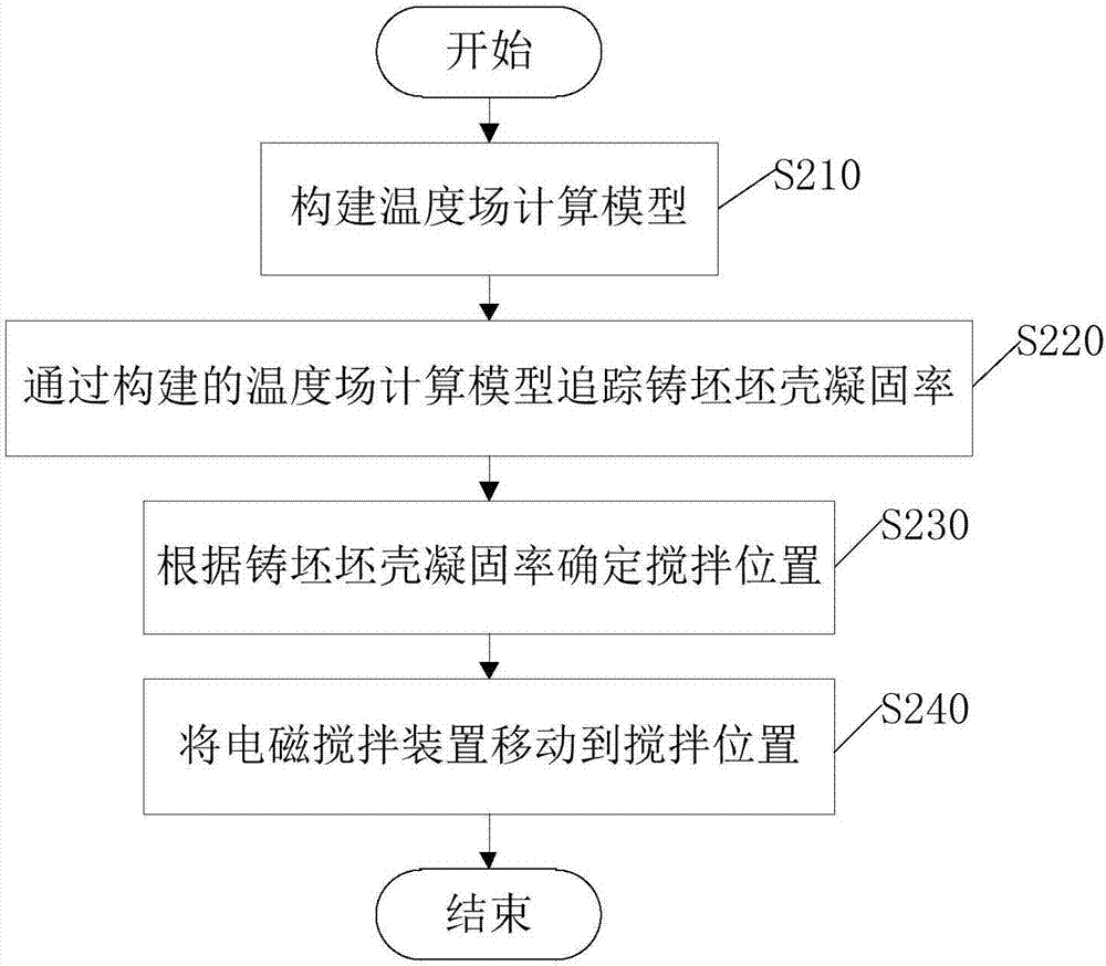
[0025] figure 2 It is a flow chart of the electromagnetic stirring control method for continuous casting of the present invention, as figure 2 As shown, the electromagnetic stirring control method for continuous casting includes:

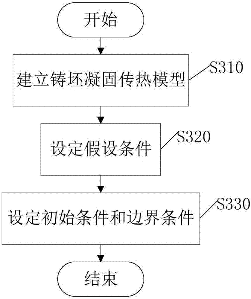
[0026] In step S210, the temperature field calculation model is constructed, and its specific process will be image 3 detailed in the description of the

[0027] After the temperatur...


PUM


Abstract

The invention provides an electromagnetic stirring control method and system for continuous casting. The method comprises the steps that a temperature field calculation model is built; the casting blank shell solidification rate is tracked through the temperature field calculation model; a stirring position is determined according to the casting blank shell solidification rate, wherein the position where the casting blank shell solidification rate is 45%-70% is determined as the stirring position; an electromagnetic stirring device is moved to the stirring position to apply an electromagnetic field to a casting blank. The system comprises an inputting unit, a model building unit, a tracing unit, a determining unit and a moving device; the inputting unit is used for inputting a technological parameter of continuous casting production, the model building unit is used for building the temperature field calculation model, the tracing unit is used for tracing the casting blank shell solidification rate according to the input technological parameter and the temperature field calculation model, the determining unit is used for determining the position where the casting blank shell solidification rate is 45%-70% as the stirring position, and the moving device is used for moving the electromagnetic stirring device to the stirring position. According to the electromagnetic stirring control method and system for continuous casting, a temperature field, the stirring device and the moving device are combined, electromagnetic stirring on the casting block at the best stirring position is achieved, and the internal quality of the casting blank is improved.

Description

technical field [0001] The invention relates to the field of continuous casting, and more specifically, to an electromagnetic stirring control method and system for continuous casting. Background technique [0002] During the continuous casting process, such as figure 1 As shown, the molten steel passes through the crystallizer 3 from the ladle 1 and the tundish 2 once to cool and crystallize to form a cast slab 100 with the solidification center of the outer shell as the molten steel and pull it out from the lower mouth of the mold 3 to form a molten steel surface 30 in the mold 3 (meniscus). After the billet 100 is pulled out from the lower opening of the crystallizer, it is subjected to secondary cooling in the secondary cooling zone, and after being straightened by the stretching and straightening roller row (note that only a part of the stretching and straightening rollers are shown in the figure), it passes through the front cutting roller table. Arrive at the torch ...

Claims


Application Information

Patent Timeline
Patent Type & Authority Patents(China)
IPC IPC(8): B22D11/18B22D11/115
Inventor 高仲白居冰
Owner CONTINUOUS CASTING TECH ENG OF CHINA
Why Eureka
Try Eureka