Bag making device

A bag-making device and heat-sealing device technology, applied in packaging and other directions, can solve the problems of increased meeting, reduced work efficiency, and difficulty in grasping the cut end of the packaging film.

Inactive Publication Date: 2015-12-09
王秀来
View PDF9 Cites 6 Cited by
  • Summary
  • Abstract
  • Description
  • Claims
  • Application Information

AI Technical Summary

Problems solved by technology

[0004] And if the bag is required to be out of the plane, then its cut end will sag. Whether it is an upper pull bag assembly or a pull down bag assembly, it is difficult to grab the cut end of the packaging film when grabbing in the horizontal direction.
Not only that, for some packaging machines that require flat packaging, in addition to the technical solution described in this reference document, a device and process that rotates the packaging bag and then sends the bag is required, and the rotation process of the packaging bag is the easiest to make the packaging bag Shifting on the rotating device, the rotating process also occupies a large space and time of the packaging machine, which will increase the height of the packaging machine and reduce work efficiency

Method used


Image

  • Bag making device
  • Bag making device
  • Bag making device

Examples


Embodiment 1

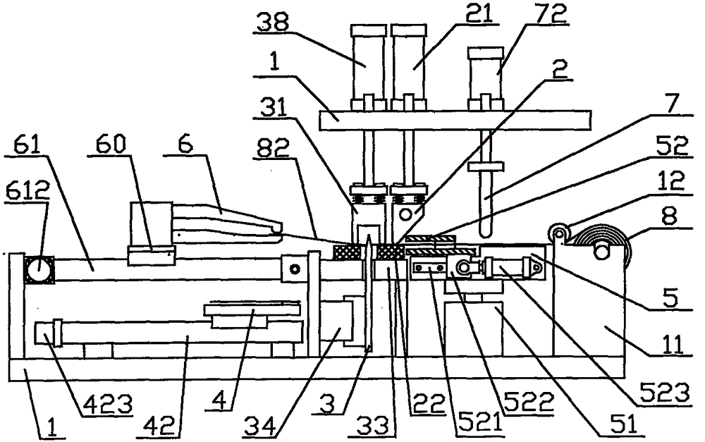
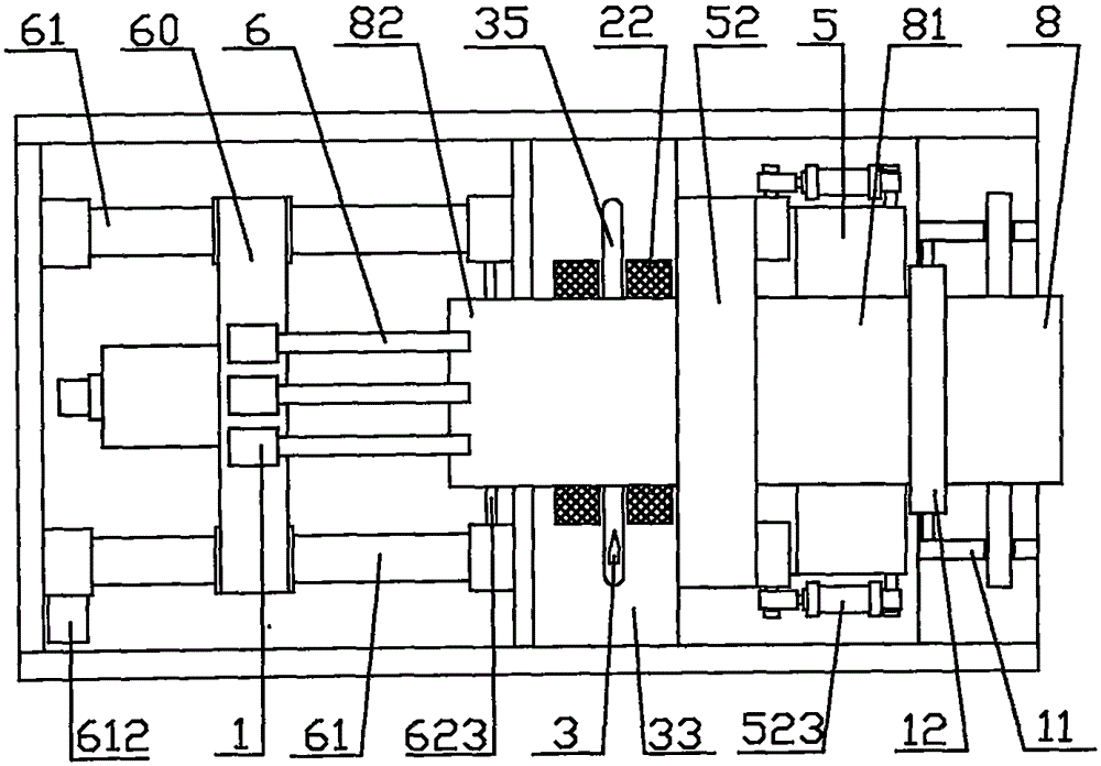
[0040] Embodiment 1: as Figure 1-Figure 8 Shown: front and rear in the present invention refer to the order from left to right in the figure, that is, the left side of the figure is the front in this description.

[0041] Install two U-shaped baffles on the left and right of the rear end of the frame 1, and set a round shaft in the two U-shaped grooves. One end of the round shaft is processed into an annular groove, and the film roll 8 is installed on the round shaft. In the middle section of the middle section, the groove of the circular shaft is placed in the U-shaped groove of the baffle plate, and a guide roller or a stop bar 12 parallel to the die roll 8 is arranged on the front side of the two baffle plates to form a film roll frame 11. The two ends of the circular shaft rotate in the U-shaped groove of the baffle with a certain frictional force to form damping, so that the bag-drawing manipulator 6 tightens the packaging film 81 during the bag-drawing process. The film...

Embodiment 2

[0049] Embodiment 2: as Figure 10 As shown: the difference between embodiment 2 and embodiment 1 is that the bag feeding mechanism is composed of an optical axis 62, a linear bearing 621, and a rodless cylinder 63; the cutting device is composed of a moving knife 36, a fixed knife 37, and a cutting cylinder 38 The fixed bag mechanism is made of cylinder 43, rocking arm 432, pressure bar 431; The bag pressing mechanism is made of pressure roller 71, rocking arm 721; set down.

[0050] An optical axis 62 is respectively installed on both sides of the frame in front of the cutting seat 33, linear bearings 621 are respectively installed on the two optical axes 62, and a bag-drawing manipulator is installed on the two linear bearings 621 on the two optical axes 62 via a beam 6. Install a rodless cylinder 63 parallel to the optical axis 62 on the inner side of the optical axis 62, and connect the cylinder slider 631 of the rodless cylinder 63 with the linear bearing.

[0051] The...

Embodiment 3

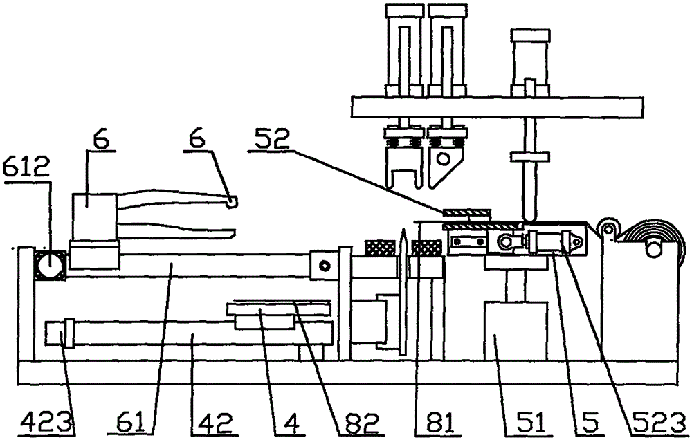
[0055] Embodiment 3: as Figure 12 As shown: the difference between embodiment 3 and embodiment 1 and embodiment 2 is that: the electric slide table 61 is lengthened and extends forward, the bag storage tray 4 is set forward and installed under the front end of the frame 1, and the delivery is omitted. Bag running mechanism; the bag storage tray 4 can also be a bag taking device on the packaging machine, or a lifting tray on the packaging machine.

[0056] The bag pressing mechanism is composed of a pressure roller 71 and a guide rod 723. The two ends of the rotating shaft of the pressure roller 71 are installed on the guide rod seat 722 with brackets, and the two guide rods 723 are slidably installed on the upper frame. Set 724. The positions of the heat-sealing device and the cutting device are mutually converted. The heat sealing cylinder 21 and the heat sealing knife 2 of the heat sealing device are installed in front of the cutting cylinder 38 and the concave pressing p...


PUM


Abstract

The invention discloses a bag making device which is mainly applied to a packing machine for making and supplying bags to the packing machine one by one. The bag making device mainly comprises a rack, a heat-sealing device, a cutting device, a film rolling frame and a guide roll. The bag making device is characterized by further comprising a bag pulling device, a bag storage disc, a connecting device and a bag fixing mechanism. The bag pulling device pulls a segment of packing film out of the work position of the heat-sealing device and the work position of the cutting device by the length of one packing bag, and a packing bag is formed after heat-sealing of the heat-sealing device and cutting of the cutting device and output to the bag storage disc; when the bag pulling device grabs the cutting end of the packing film next time, the connecting device lifts up the cutting end of the packing film so that the packing film can horizontally correspond to a bag pulling mechanical arm, and the packing film can be grabbed reliably. The bag making device has the advantages of being simple and compact in structure, stable and reliable in operation of making bags one by one in sequence, capable of outputting bags in a plane and the like.

Description

technical field [0001] The invention relates to the field of bag making for packaging bags, in particular to a bag making device for a packaging machine. Background technique [0002] The bag-making device involved in the present invention is mainly applied to a packaging machine, and is used to provide packaging bags to the packaging machine one by one in sequence. The traditional bag making machine must be equipped with a set of bulky pre-discharging device. The upper and lower sets of rubber rollers are driven by stepping or servo motors to rotate at high speed. The working position of the device shoots out a section, and then the motor drives the crank linkage mechanism to move the heat-sealing knife and cutter down to heat-seal the predetermined sealing line position of the packaging film and cut it to form a packaging bag. This bag making machine is bulky and complex in structure and cannot be adapted to a packaging machine. [0003] Application publication number: C...

Claims


Application Information

Patent Timeline
Patent Type & Authority Applications(China)
IPC IPC(8): B65B47/00
CPCB65B47/00
Inventor 王秀来
Owner 王秀来
Why Eureka
Try Eureka