Check patentability & draft patents in minutes with Patsnap Eureka AI!

A construction method for a multi-directional adjustable cast-in-place box girder support system for oblique-span low-clearance active highways

A low-headroom, multi-directional technology, used in bridges, bridge construction, erection/assembly of bridges, etc., can solve the problem of dead fixed trusses, inability to adjust the vertical and horizontal positions of the trusses, and inability to meet the strain. requirements and other issues, to achieve the effect of ensuring synergistic force deformation, ensuring motion consistency, and simplifying the construction process

Active Publication Date: 2016-08-24
JIANGXI PROVINCE LUQIAO ENG GRP
View PDF5 Cites 0 Cited by
  • Summary
  • Abstract
  • Description
  • Claims
  • Application Information

AI Technical Summary

Problems solved by technology

[0003] At present, a cast-in-place box girder construction technology with brackets is often used to deal with the complexity of the current construction. This type of bracket is composed of temporary buttresses, stressed trusses, suspension systems and formwork, and can meet the requirements of driving under the bridge through a reasonable design layout. Clearance and roadway width requirements. In this scheme, the position of the force truss is related to the size of the traffic clearance under the bridge and the width of the roadway. However, the force truss in this scheme is fixed. Once the support construction is completed After that, the vertical and horizontal positions of the stressed trusses cannot be adjusted. Therefore, if special circumstances occur during bridge construction and the angle and orientation need to be adjusted, the position of the fixed stressed trusses may not be able to meet the strain requirements.

Method used


Image

  • A construction method for a multi-directional adjustable cast-in-place box girder support system for oblique-span low-clearance active highways
  • A construction method for a multi-directional adjustable cast-in-place box girder support system for oblique-span low-clearance active highways
  • A construction method for a multi-directional adjustable cast-in-place box girder support system for oblique-span low-clearance active highways

Examples


Embodiment Construction

[0023] The technical scheme of the present application will be specifically described below in conjunction with the accompanying drawings and embodiments:

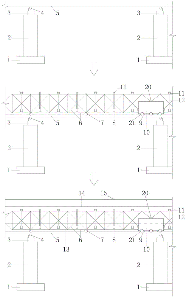
[0024] A bridge under construction is inclined at 30° to the active road, and the design clearance is 5.8m. The bridge is constructed with prestressed concrete continuous box girder. The clear road width cannot be less than 10m, and the driving clearance cannot be less than 5.0m. In order to meet the above requirements, the mobile adjustable cast-in-place box girder support system of the oblique-span low-clearance active road used in the present invention, its specific construction and implementation process are as follows:

[0025] refer to figure 1 , set the foundation 1 with length×width×height=2.2m×1.1m×0.8m in the parking lane and the middle zone on both sides of the active road, the span of foundation 1 along the box girder direction is 11.5m, With a span of 6.75m along the highway, double steel pipes with a length...


PUM


Abstract

The invention discloses a construction method for a diagonal-span low-clearance road-on-duty multi-azimuth adjustable cast-in-place box beam support system. The method comprises the following steps: arranging foundations and establishing temporary piers on stopways and medium dividers in advance, arranging wide-range high-precision electronic oil jacks on the tops of the temporary piers, arranging a track through fixing feet, using a Bailey beam or a military beam to make a force-bearing truss, after installing suspenders and lower hanging beams on the force-bearing truss, arranging sliding wheels at certain interval on the lower part of the truss, and arranging a driving electric car, the force-bearing truss and the driving electric car being fixed by a connecting end, and arranging template supports on the force-bearing truss and the lower hanging beams, installing a bottom die, side dies, an inner die, and end dies, to complete construction of the cast-in-place box beam support. The method realizes multi-azimuth adjustment of the cast-in-place box beam support, and can control clearance on site in real time, and normal operation of a road is not influenced.

Description

technical field [0001] The invention relates to a construction method of a cast-in-place box girder support, in particular to a construction method of a multi-directional adjustable cast-in-place box girder support system for an oblique-span low-clearance active road. Background technique [0002] In recent years, more and more bridges need to be cast-in-place constructed obliquely or across active roads. Generally, oblique or spanning bridges are required to meet certain clearance standards and span standards. During the construction process, the road cannot be blocked, and the normal operation of the road cannot be affected. Operation, so as not to affect the convenience and safety of highway driving, limited by the above-mentioned many factors, the support erection in the construction of cast-in-place box girder has always been the focus and difficulty in construction. [0003] At present, a cast-in-place box girder construction technology with brackets is often used to d...

Claims


Application Information

Patent Timeline
Patent Type & Authority Patents(China)
IPC IPC(8): E01D21/00
Inventor 王新泉
Owner JIANGXI PROVINCE LUQIAO ENG GRP
Features
  • R&D
  • Intellectual Property
  • Life Sciences
  • Materials
  • Tech Scout
  • Unparalleled Data Quality
  • Higher Quality Content
  • 60% Fewer Hallucinations
Learn More