Dispersion Phase Compensation Method for Laser Frequency Scanning Interferometer Based on Focusing Definition Evaluation Function
A technology of frequency scanning interference and focusing definition, which is applied in the direction of instruments, optical devices, measuring devices, etc., can solve the problems of low measurement resolution and measurement signal influence, and achieve the effect of large-scale high-resolution measurement
- Summary
- Abstract
- Description
- Claims
- Application Information
AI Technical Summary
Problems solved by technology
Method used
Image

Examples
specific Embodiment approach 1
[0022] Specific implementation mode one: the dispersion phase compensation method based on the focusing sharpness evaluation function, which is implemented in the following steps:
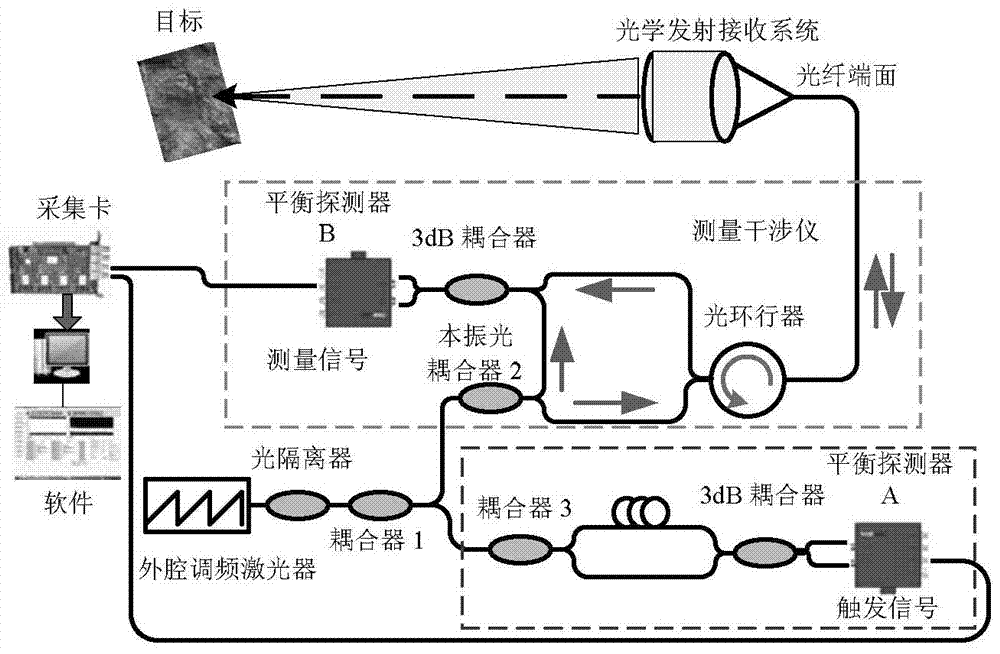
[0023] (3) Establish the beat frequency model of the measurement signal under the fiber dispersion condition of the high-resolution laser frequency scanning interferometer;
[0024] (4) Compensate the optical fiber dispersion of the beat frequency model of the measurement signal by using the phase method:
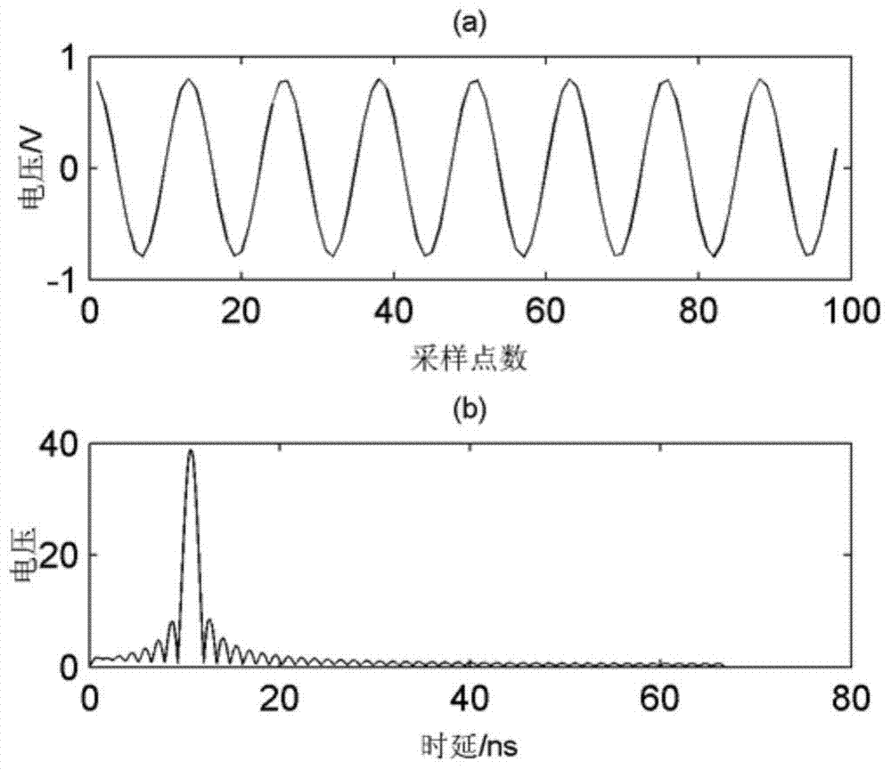
[0025] (1) The measured signal is multiplied by the complex phase compensation item, and the dispersion phase distortion in the measured signal is compensated by adjusting the dispersion compensation coefficient. When the dispersion phase distortion of the measured signal is compensated, the full width at half maximum of the frequency spectrum of the signal will be narrowed;
[0026] (2) The focusing sharpness evaluation function is proposed as a criterion for judging whether the phase distortio...
specific Embodiment approach 2
[0031] Specific implementation mode two: the difference between this implementation mode and specific implementation mode one is: step (1) is specifically:
[0032] (1) The beat frequency ω formed by the auxiliary interferometer of the high-resolution laser frequency scanning interferometer aux Expressed as formula (6):
[0033]
[0034] Among them, the τ aux Indicates the time delay corresponding to the length difference of the two fiber arms in the auxiliary interferometer, μ is the frequency modulation slope, β 2 =-20ps 2 / km represents the group velocity dispersion of single-mode fiber, υ g Indicates the group velocity, t indicates the frequency modulation time of the laser;
[0035] (2) Since the beat frequency of the measuring interferometer and the auxiliary interferometer is directly proportional to the time delay, after sampling the measurement signal using the frequency sampling method, the delay ratio between the measuring interferometer and the auxiliary int...
specific Embodiment approach 3
[0044] Specific implementation mode three: the difference between this implementation mode and specific implementation mode one or two is: step (2) (1) is specifically:
[0045] (1) indicates that after adjusting the phase compensation factor each time, calculate the S value to see if it reaches the maximum value, and when the S value is the maximum, it is considered that the dispersion compensation is completed. However, in this process, a fixed step size is usually set to change the phase compensation factor, and the S value is judged each time until the S value reaches the maximum, and the compensation speed is relatively slow. And (2) the method of thirds avoids setting a fixed step size, and the maximum value of S can be found through fewer calculation times. Therefore, the method of thirds improves the efficiency of compensation.
[0046]Dispersion compensation is realized by calculating whether the S value of the focusing sharpness evaluation function reaches the maximu...
PUM
 Abstract
Description
Claims
Application Information
 - R&D
- Intellectual Property
- Life Sciences
- Materials
- Tech Scout
- Unparalleled Data Quality
- Higher Quality Content
- 60% Fewer Hallucinations
Browse by: Latest US Patents, China's latest patents, Technical Efficacy Thesaurus, Application Domain, Technology Topic, Popular Technical Reports.
© 2025 PatSnap. All rights reserved.Legal|Privacy policy|Modern Slavery Act Transparency Statement|Sitemap|About US| Contact US: help@patsnap.com