
Optical lens and light-emitting device using the optical lens

An optical lens and lens technology, applied in optics, lighting devices, optical components, etc., can solve problems such as insufficient light intensity and dark bands

Active Publication Date: 2015-12-09
WT MICROELECTRONICS
View PDF6 Cites 3 Cited by
  • Summary
  • Abstract
  • Description
  • Claims
  • Application Information

AI Technical Summary

Problems solved by technology

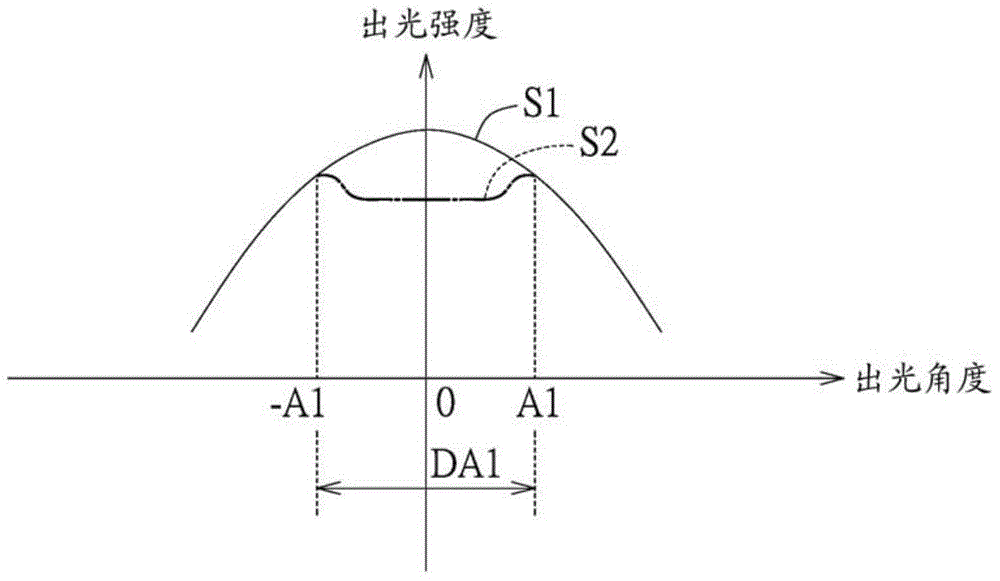
However, expanding the angle of light emission can easily lead to the problem of insufficient light intensity of light emitted from a small angle, and then the phenomenon of dark bands

Method used


Image

  • Optical lens and light-emitting device using the optical lens
  • Optical lens and light-emitting device using the optical lens
  • Optical lens and light-emitting device using the optical lens

Examples


Embodiment Construction

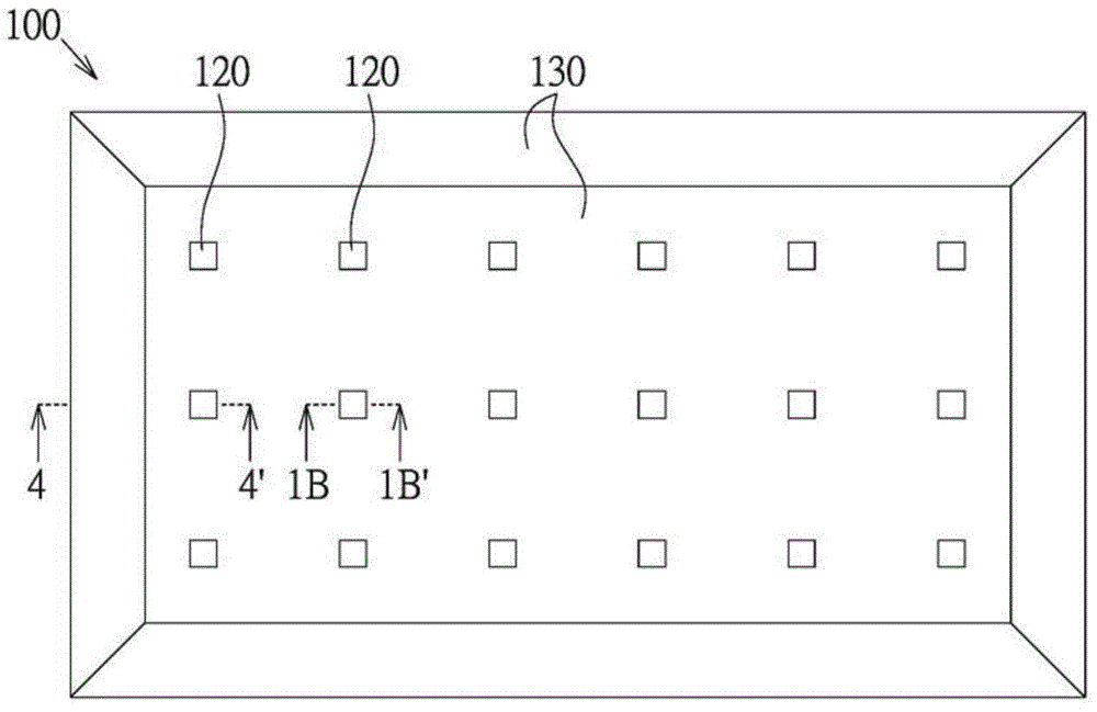
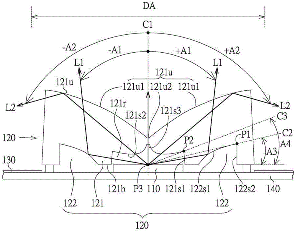
[0051] Please refer to Figure 1A and Figure 1B , Figure 1A shows a top view of a light emitting device according to an embodiment of the present invention, and Figure 1B draw Figure 1A A cross-sectional view along direction 1B-1B'. The light-emitting device 100 is, for example, a part of a direct-lit backlight module, which includes several light-emitting elements 110 , several optical lenses 120 , reflectors 130 and a circuit board 140 . In addition, the optical lens 120 and the reflective sheet 130 of the embodiment of the present invention are not limited to be applied to the direct type backlight module, and they can also be applied to the edge type backlight module, or other lighting devices other than the backlight module.

[0052] The light emitting element 110 is, for example, a light emitting diode. In this embodiment, several light emitting elements 110 are disposed on the circuit board 140 and arranged in an array. In another embodiment, several light emitti...


PUM


Abstract

The present invention discloses an optical lens and a light-emitting device using the optical lens. The optical lens includes a bottom face, a light-emitting face and a full reflecting face. The full reflecting face extends from the bottom to outer side and is towards to the light-emitting face. According to the full reflecting face, the light-emitting angle of the light reflected by the full reflecting face is less than 150 degrees so that a dark band region is supplied with a light intensity.

Description

technical field [0001] The invention relates to an optical lens and a light-emitting device using the optical lens, in particular to an optical lens with a total reflection surface and a light-emitting device using the optical lens. Background technique [0002] The traditional optical lens is used to expand the light angle of the light, so that the irradiation range of the light is expanded. However, expanding the light output angle easily leads to the problem of insufficient light intensity of light output from a small angle, and then the dark band phenomenon occurs. Contents of the invention [0003] The object of the present invention is to provide an optical lens and a light emitting device using the optical lens, which can supplement the insufficient light intensity in the dark band area. [0004] According to an embodiment of the present invention, an optical lens is provided. The optical lens includes a bottom surface, a light emitting surface and a total reflect...

Claims


Application Information

Patent Timeline
Patent Type & Authority Applications(China)
IPC IPC(8): G02B17/08F21V5/00F21Y101/02
Inventor 张维典
Owner WT MICROELECTRONICS
Learn More