Light guide plate and backlight module using light guide plate

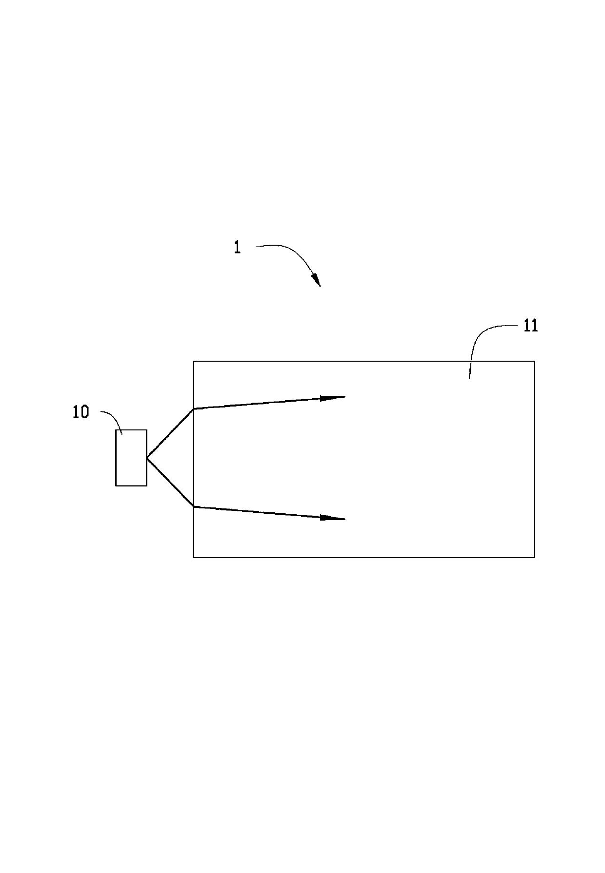
A technology of backlight module and light guide plate, which is applied in the directions of optics, light guide, light source, etc., can solve the problems of reducing the diffusion angle and reducing the light utilization rate of the light guide plate 11, etc.

Inactive Publication Date: 2014-06-18
HONG FU JIN PRECISION IND (SHENZHEN) CO LTD +1
View PDF4 Cites 1 Cited by
  • Summary
  • Abstract
  • Description
  • Claims
  • Application Information

AI Technical Summary

Problems solved by technology

Since the light emitting angle of the light emitting diode light source 10 is relatively fixed, and the light guide plate 11 is usually a thin plate (generally only a few millimeters) made of acrylic, glass or polycarbonate and other transparent materials with a high refractive index, when the light emitting diode light source When the light emitted by 10 is refracted into the light guide plate 11 through the light incident surface of the light guide plate 11, the diffusion angle of the light emitted by the LED light source 10 in the lateral direction of the light guide plate 11 will become smaller, so that the edges on both sides of the light guide plate 11 will be Can not effectively illuminate and produce dark bands, which reduces the light utilization efficiency of the light guide plate 11

Method used


Image

  • Light guide plate and backlight module using light guide plate
  • Light guide plate and backlight module using light guide plate
  • Light guide plate and backlight module using light guide plate

Examples


Embodiment Construction

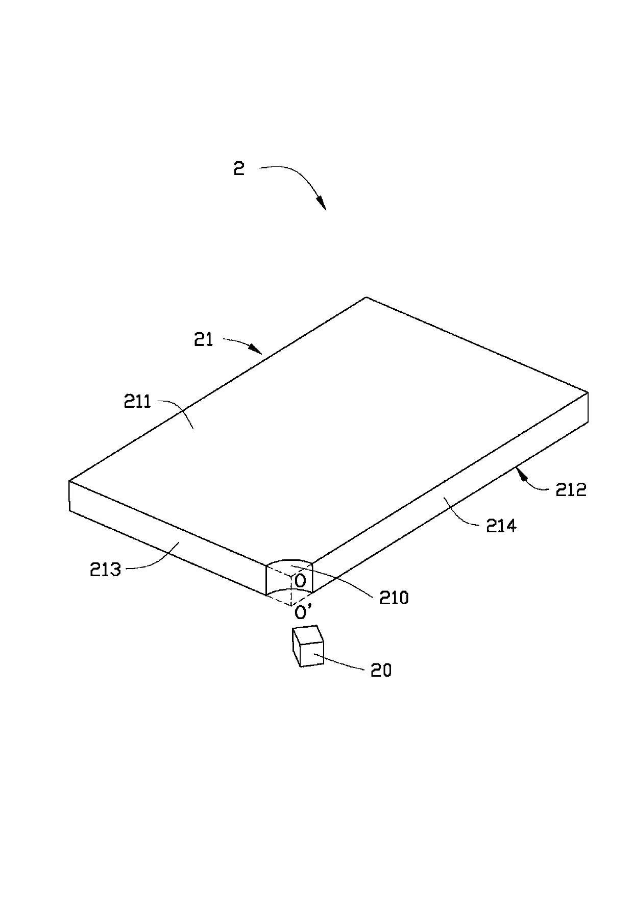
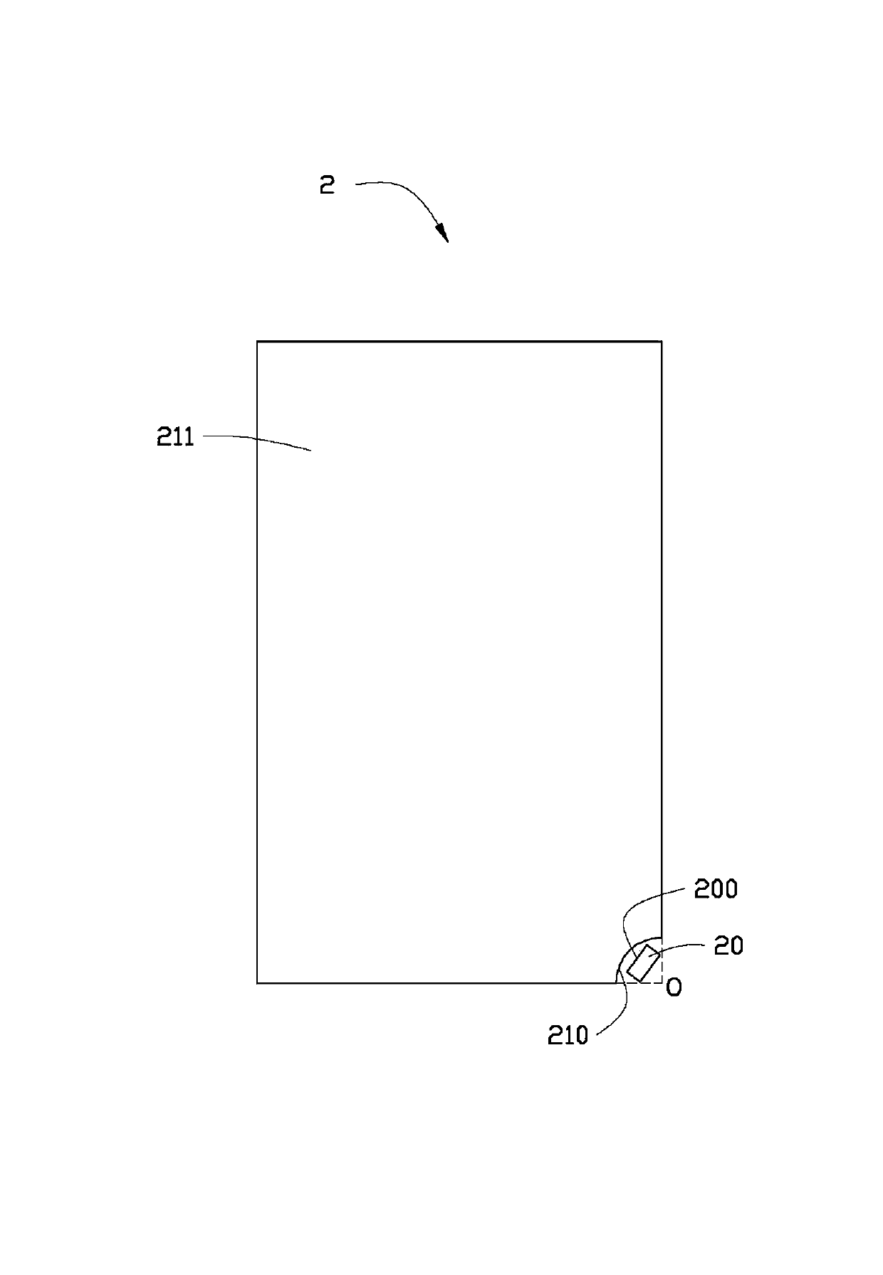
[0020] see Figure 2 to Figure 4 , the backlight module 2 of the first embodiment of the present invention includes a light guide plate 21 and an LED light source 20 disposed facing the light guide plate 21 . The LED light source 20 is used to generate incident light beams entering the light guide plate 21 . The light guide plate 21 includes a light incident surface 210 for receiving incident light beams, a light exit surface 211 adjacent to the light incident surface 210 , and a bottom surface 212 opposite to the light exit surface 211 . The light incident surface 210 and the light output surface 211 are perpendicular to each other.

[0021] The light guide plate 21 is a cuboid. The light incident surface 210 is formed by a corner of the light guide plate 21 being recessed toward the inside of the light guide plate 21 . The light incident surface 210 is an arc surface, and the light incident surface 210 faces away from the incident direction of the incident light beam and ...


PUM


Abstract

A light guide plate comprises a light incidence face for receiving incident light beams, a light emission face adjacent to the light incidence face and a bottom face opposite to the light emission plate. The light incidence face is perpendicular to the light emission face and formed by sinking of the peripheral face of the light guide plate towards the interior of the light guide plate. The incident light beams are subjected to incidence into the light guide plate through the light incidence face and are refracted towards sides adjacent to the light incidence face to form uniform light field distribution on the section of the light guide plate parallel to the light emission face. The invention further provides a backlight module using the light guide plate. According to the light guide plate and the backlight module, the light incidence face is sunken towards the interior of the light guide plate from the peripheral face of the light guide plate, and the incident light beams are subjected to incidence into the light guide plate through the light incidence face and are refracted towards the two sides of the light guide plate, so that dark zones at the edges of the light guide plate can be effectively reduced, and the light ray utilization rate of the light guide plate can be improved.

Description

technical field [0001] The invention relates to the field of liquid crystal display, in particular to a light guide plate and a backlight module using the light guide plate. Background technique [0002] Light emitting diodes (light emitting diodes, LEDs), as an efficient light source, have many characteristics such as environmental protection, power saving, and long life, and have been widely used in various fields, especially in the field of display imaging. Light emitting diodes are often used Used as the backlight of the backlight module. [0003] Such as figure 1 As shown, the LED backlight module 1 in the prior art generally includes a light guide plate 11 and an LED light source 10 disposed on one side of the light guide plate 11 . The light emitted by the LED light source 10 enters into the light guide plate 11 through the light incident surface of the light guide plate 11 . Since the light emitting angle of the light emitting diode light source 10 is relatively f...

Claims


Application Information

Patent Timeline
Patent Type & Authority Applications(China)
IPC IPC(8): F21V8/00F21S8/00F21Y101/02F21Y115/10
Inventor 陈柏洲
Owner HONG FU JIN PRECISION IND (SHENZHEN) CO LTD
Why Eureka
Try Eureka