A method of making a microprism mold that reduces the dark band of the seam

A technology of patchwork dark zone and production method, which is applied in the direction of manufacturing tools, metal processing equipment, welding equipment, etc., can solve the problems of large ineffective reflective area, reduce mold patchwork dark zone, etc., achieve wide application range, reduce non-reflective Dark band width, the effect of reducing the dark band width

Active Publication Date: 2021-11-02
福建跃发光新材料股份有限公司
View PDF5 Cites 2 Cited by
  • Summary
  • Abstract
  • Description
  • Claims
  • Application Information

AI Technical Summary

Problems solved by technology

[0011] The embodiment of the present application provides a method for making a microprism mold that reduces the dark band of the seam, which solves the problem in the prior art of cutting the mold sheet with rough machining technology, resulting in a large invalid reflection area, and realizes the reduction of the mold. Patchwork dark bands, and then reduce the width of the non-reflective dark bands of the reflective original film formed after the optical film is planted, and improve the overall reflective efficiency of the microprism reflective film

Method used


Image

  • A method of making a microprism mold that reduces the dark band of the seam
  • A method of making a microprism mold that reduces the dark band of the seam
  • A method of making a microprism mold that reduces the dark band of the seam

Examples


Embodiment 1

[0052] A method of making a microprism mold patchwork dark bands is reduced, comprising the steps of:

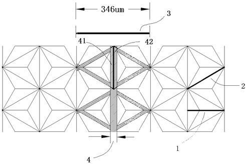
[0053] (1) See Image 6 Selecting an initial template microprisms 5, and placed under a microscope, the microscope magnification adjustment until clearly observed microprism initial template 5, the direction of observation of the initial template 5 pyramid microprisms and array of microprisms fine V-groove where the direction of the tool machining path marked direction and the distance m, the processing to be simultaneously measured initial template 5 microprism thickness d (d refers to the distance a fine non-tapered angle V to the bottom of the trench), and measuring the fine grooves V groove angle a.

[0054] (2) used to select the finishing cutter, the cutter blade is V-shaped, V-shaped cross section, and is mounted to the cutting tool path running gear.

[0055] (3) See Figure 5 , To be processed microprism initial template 5 is attached to the precision of the cutting posit...

Embodiment 2

[0062] A method of making a microprism mold patchwork dark bands is reduced, comprising the steps of:

[0063] (1) Select a microprism initial template 5, and placed under a microscope, the microscope magnification adjustment until clearly observed microprism initial template 5, the direction of observation of the initial template 5 pyramid microprisms and array of microprisms fine V where the direction of the grooves, the tool machining path marked direction and the distance m, the processing to be simultaneously measured initial template 5 microprism thickness d (d refers to the distance to the bottom of the trench non-fine-V cone angle), and the measured minute V-groove angle a, the size of a unit pyramid, pyramid means ineffective reflective section dimensions L1, see Figure 11 Indicated.

[0064] (2) used to select the finishing cutter, the cutter blade is V-shaped, V-shaped cross section and is mounted to the cutting tool path running gear.

[0065] (3) See Figure 5 , To be ...


PUM


Abstract

The invention discloses a method for making a microprism mold that reduces the dark band of the seam, and particularly relates to the way of finishing through ultra-precision cutting equipment, using a V-shaped triangular cutter along the micro-V groove of the microprism initial mold with a pyramid array The groove path is divided and cut into mold pieces or mold strips for manufacturing working molds of various specifications such as yin and yang stripes and square grids, providing a cutting method that maintains the integrity of the unit microprism pyramid and maximizes the integrity of the effective reflective area of ​​the unit pyramid, reducing The width of the dark belt of the non-reflective patchwork of the working mold can effectively improve the overall reflective efficiency of the working mold, and then produce micro-prism reflective films with various appearances such as yin and yang stripes and squares with high reflective efficiency, high integrity, and high consistency.

Description

Technical field [0001] The present invention relates to the field of optical mold manufacturing, and more particularly to a method of manufacturing a microprism mold that reduces the seam tape. Background technique [0002] The vertex of the full cell pyramid is not reflective in which the light is irradiated in one side of the concave angular cone, and the three sides of the three nanoscale smooth extents in the concave corner cone are generated, and three specular reflections Returning along the original road, but when the light is irradiated in the lowest point of the positive angle, the vertex of the ridges, the three sides are gathered in the spatial space, and the light is narrow, and the light is reflected in this space. The reflected light is bound here, there is no way to reflect the source, thereby generating a reflective invalid zone; and the angular point of the reede, adjacent to the third side, so that the light is irradiated in the concave pierveral cone angle. Nea...

Claims


Application Information

Patent Timeline
Patent Type & Authority Patents(China)
IPC IPC(8): B23P15/24B23K26/24
CPCB23K26/24B23P15/24
Inventor 梁桂德许明旗黄志鹏黄志江朱庆强蔡佳旺
Owner 福建跃发光新材料股份有限公司
Why Eureka
Try Eureka