
Backlight module

A technology of backlight module and light-emitting module, which is applied in the direction of light guide, optics, optical components, etc., can solve the problems of use, easy detection of dark bands, etc., and achieve the effect of improving the effect of dark bands on the edge

Pending Publication Date: 2020-05-19
AU OPTRONICS CORP
View PDF13 Cites 2 Cited by
  • Summary
  • Abstract
  • Description
  • Claims
  • Application Information

AI Technical Summary

Problems solved by technology

A reflective sheet is usually placed on the wall of this mechanical component to reflect light to the diffuser plate and avoid possible color lines or surface unevenness (MURA). However, due to the aforementioned structural configuration, the diffuser plate is placed on the platform of the mechanical component The part or area on the upper part, which is not easy for light to enter, thus forming a dark band visually
Therefore, there will be dark bands around the display device, and as the side width becomes narrower, the dark bands generated by the platform will be more easily detected, causing problems in use.

Method used


Image

  • Backlight module
  • Backlight module
  • Backlight module

Examples


Embodiment Construction

[0058] In order to facilitate the understanding of the technical features, content and advantages of the present invention and the technical effects that can be achieved, the present invention is hereby combined with the accompanying drawings, and is described in detail as follows in the form of embodiments, and the accompanying drawings used herein, its gist It is only for the purpose of illustration and auxiliary description, not necessarily the true proportion and precise configuration of the present invention after implementation, so the attached drawings should not be interpreted based on the proportion and configuration relationship of the attached drawings, and the claims that limit the actual implementation of the present invention are complied with. Explain first.

[0059]In the drawings, the thickness or width of layers, films, panels, regions, etc., are exaggerated for clarity. Throughout the specification, the same reference numerals denote the same elements. It w...


PUM


Abstract

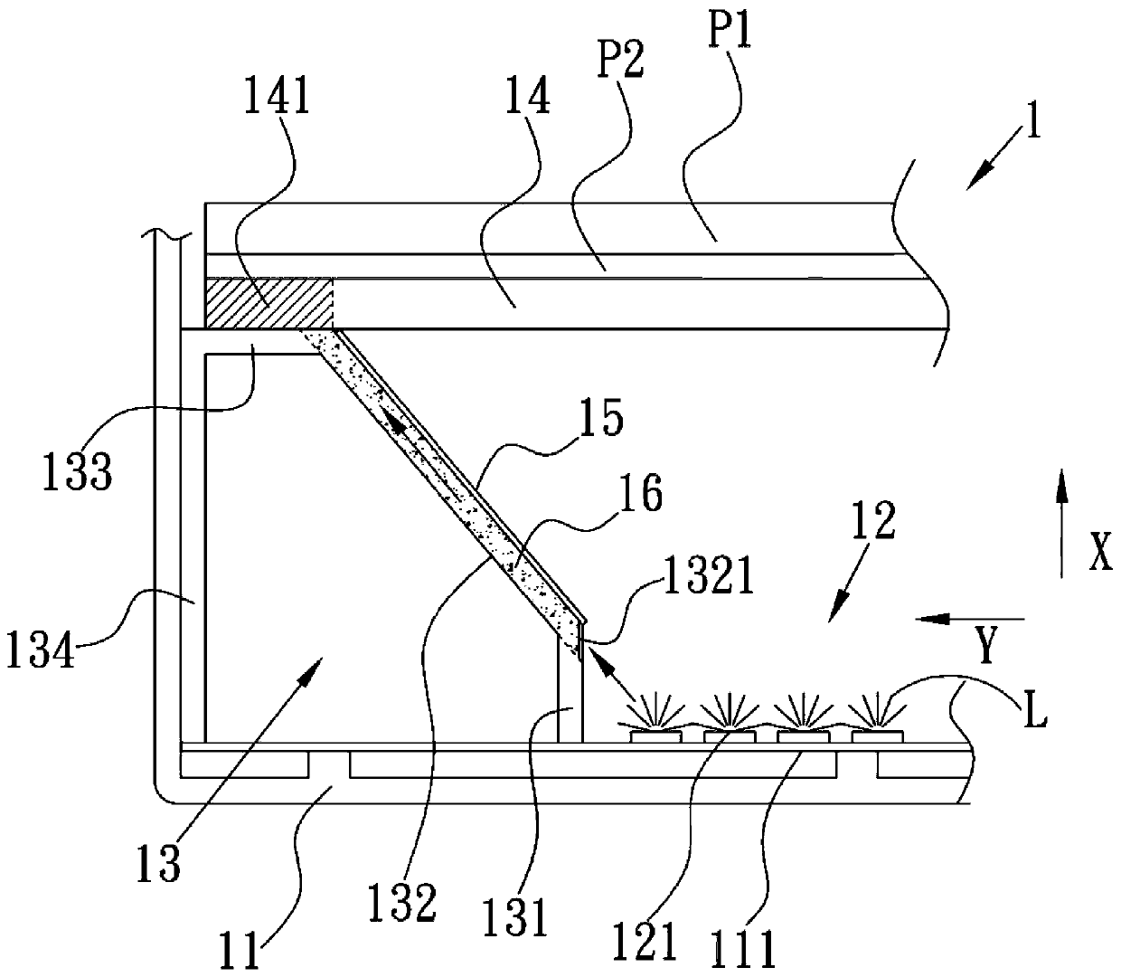
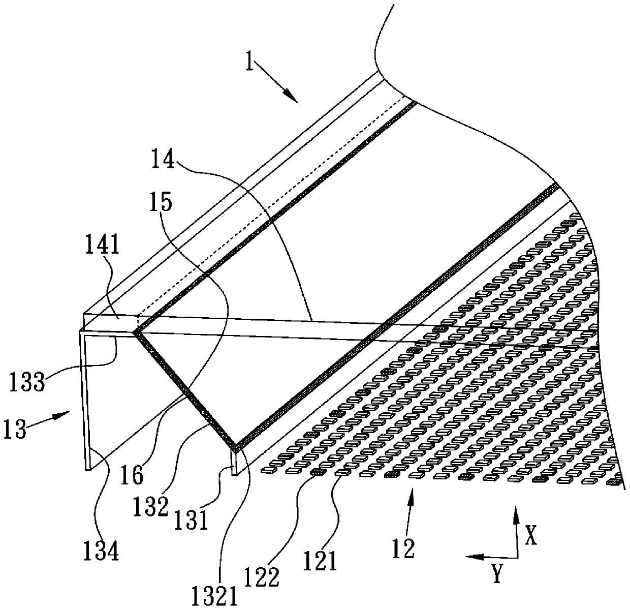
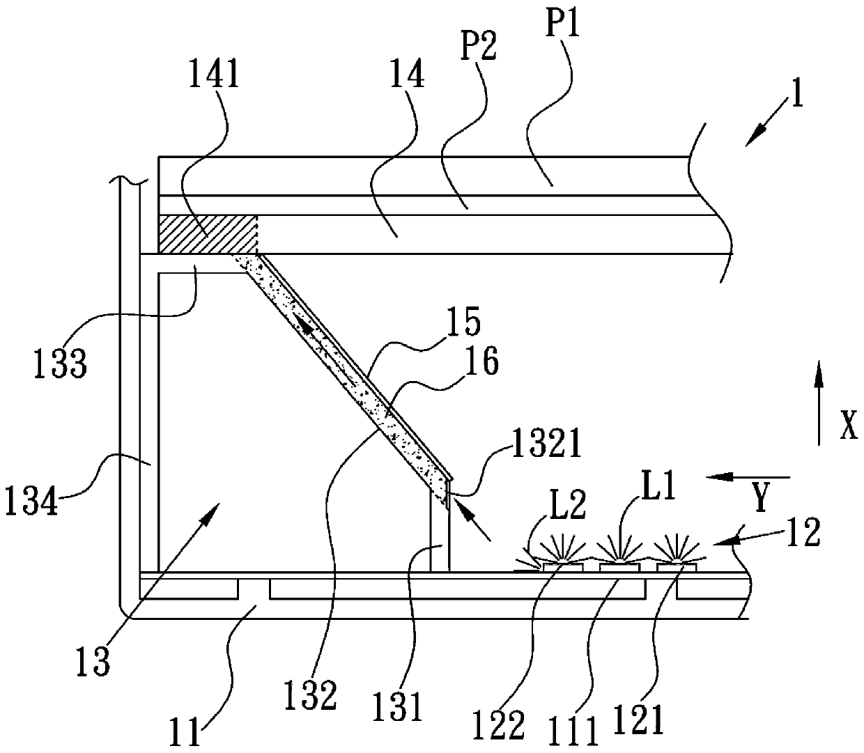
The invention discloses a backlight module. The backlight module includes a light emitting module, a support frame, a diffusion plate and a light guide. The light emitting module is arranged on a substrate and emits light. The support frame has a first support part, a diagonal part, a bearing part and a second support part connected in sequence. The first support part is adjacent to the light emitting module. The diffusion plate bears against the bearing part to receive light, and the area where the diffusion plate bears against the bearing part is formed as a bearing area. The light guide isprovided at least in the diagonal part, or at least in the bearing part, so that the light is transmitted to the bearing area. Therefore, the backlight module can improve the dark bands on the edge ofthe display surface of a display.

Description

technical field [0001] The invention relates to the technical field of a display, in particular, the invention relates to a backlight module capable of improving the problem of dark bands at the edge of a display surface of a display. Background technique [0002] With the continuous improvement of requirements for specifications such as resolution and narrow bezel, the optical configuration in the display device is also tested. [0003] Traditionally, the backlight modules of display devices can be roughly divided into two types: edge-lit and direct-lit. Among them, the direct-lit backlight modules mostly form a platform around the periphery with mechanical components, so that the platform can be used to carry the diffuser plate. , Optical films and display panels and other components. A reflective sheet is usually placed on the wall of this mechanical component to reflect light to the diffuser plate and avoid possible color lines or surface unevenness (MURA). However, due...

Claims


Application Information

Patent Timeline
IPC IPC(8): G09F9/00G02B6/00
CPCG02B6/0001G09F9/00
Inventor 陈智昇
Owner AU OPTRONICS CORP
Learn More