
Backlight module and liquid crystal display

A backlight module and light source technology, applied in optics, light guides, optical components, etc., can solve the problems of large energy consumption and occupying space, limited brightness of backlight modules, etc., to achieve small occupied space, reduce dark band generation, and improve light source. effect of brightness

Inactive Publication Date: 2006-06-21
HONG FU JIN PRECISION IND (SHENZHEN) CO LTD +1
View PDF0 Cites 3 Cited by
  • Summary
  • Abstract
  • Description
  • Claims
  • Application Information

AI Technical Summary

Problems solved by technology

[0009] In order to solve the shortcomings of the prior art backlight modules such as limited luminous brightness, high energy consumption and space occupation, the purpose of the present invention is to provide a backlight module structure, which adopts a field emission light source, which can increase the brightness by 10 to 1000 times, and save Power consumption, reduce space occupation

Method used


Image

  • Backlight module and liquid crystal display
  • Backlight module and liquid crystal display
  • Backlight module and liquid crystal display

Examples


Embodiment Construction

[0022] The present invention will be described in detail below in conjunction with the accompanying drawings and specific embodiments.

[0023] The present invention uses a field emission light source to replace the EL, CCFL or LED in the prior art to form a backlight module of a liquid crystal display device.

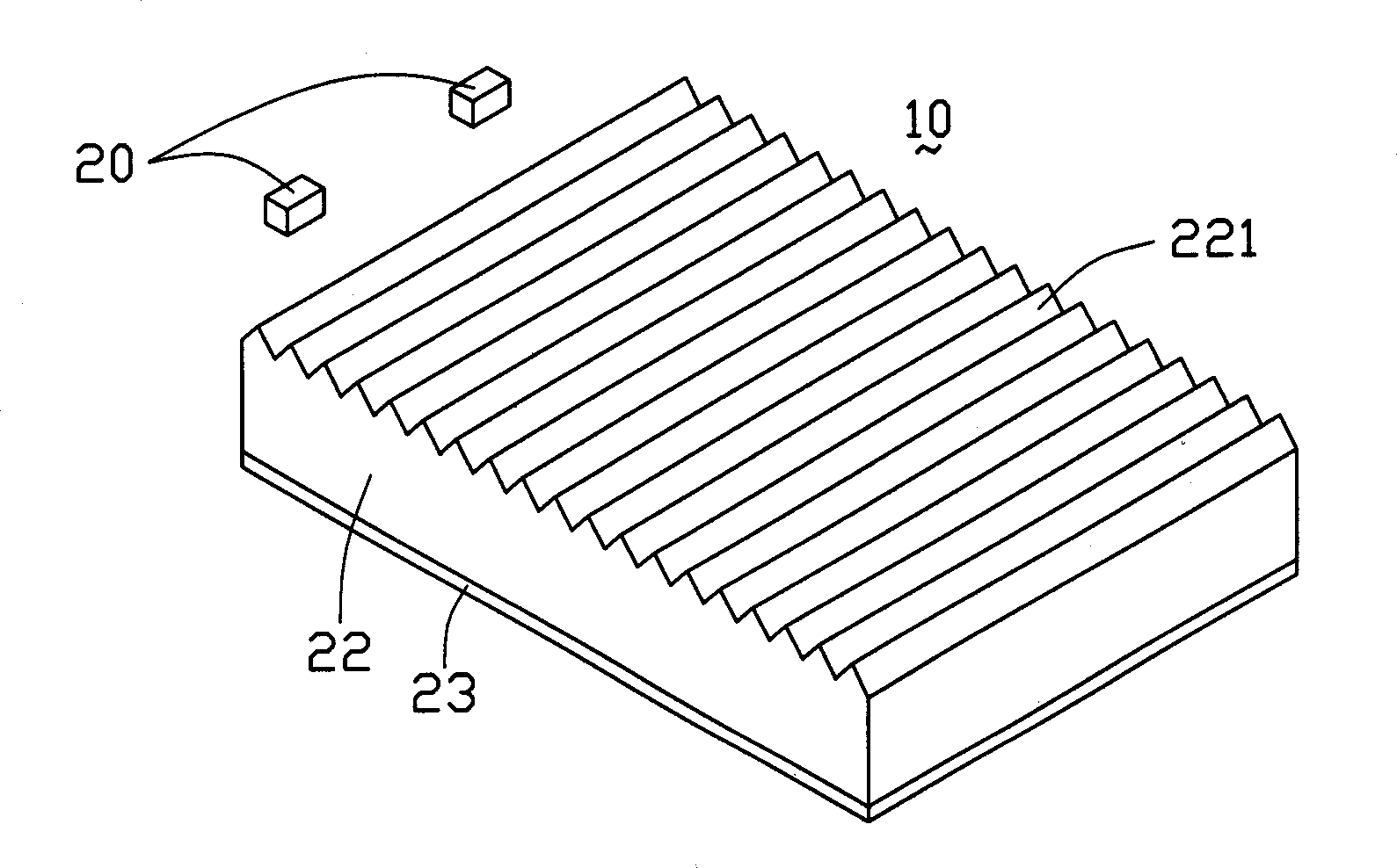
[0024] see Figure 4 , is a three-dimensional schematic diagram of the backlight module 100 of the present invention, including a field emission light source 110 and a light guide plate 101 . Of course, according to needs, the backlight module 100 of the present invention may also include elements such as reflectors, diffusers, and light collectors (not shown in the figure), Figure 4 Only the light source and the light guide plate are shown in the figure. In the figure, the light guide plate 101 includes an outgoing surface 102 , a reflective bottom surface 105 opposite to the outgoing surface 102 , two pairs of reflective side surfaces 103 and 107 , 104 and 106 , a...


PUM

PropertyMeasurementUnit
diameteraaaaaaaaaa
lengthaaaaaaaaaa

Abstract

The invention discloses an aphototropism mould and LCD, which consists of light conducting plate and a place of launching light source, wherein the aphototropism mould contains a light conducting plate, which possesses the emergent face, incidence face, several reflective sides and bottom; when the launching light source is under bias voltage action, the electronic launching body emits electron to bombard the fluorescence layer to generate visible light, which incidences the incidence face of light conducting plate through emergent face. The invention improves the light source brightness and saves the power consumption, which occupies small space and reduces the dark band appearance.

Description

【Technical field】 [0001] The invention relates to a liquid crystal display, in particular to a backlight module of the liquid crystal display and a liquid crystal display device using the backlight module. 【Background technique】 [0002] In recent years, liquid crystal displays have been widely used, such as liquid crystal monitors and liquid crystal TVs. Since the liquid crystal in the LCD panel itself does not have luminous properties, in order to achieve the display effect, it is necessary to provide the LCD panel with a light source device, such as a backlight module, whose function is to provide the LCD panel with a surface with sufficient brightness and uniform distribution. light source. [0003] Generally speaking, the backlight module can be divided into side-light structure and direct-light structure according to the distribution position of the light tubes. The edge-lit type is mainly used in small-sized panel displays (such as mobile phone LCD screens), while t...

Claims


Application Information

Patent Timeline
Patent Type & Authority Applications(China)
IPC IPC(8): G02F1/1335
CPCG02B6/0038G02B6/0061G02B6/0066H01J61/305H01J63/02
Inventor 陈杰良
Owner HONG FU JIN PRECISION IND (SHENZHEN) CO LTD
Learn More