A tightly fitting mold clamp for injection molds

A technology of injection molds and mold clamps, which is applied in the field of injection mold clamps to prevent losses or potential safety hazards

Inactive Publication Date: 2018-04-13
钟锋良 +1
View PDF3 Cites 0 Cited by
  • Summary
  • Abstract
  • Description
  • Claims
  • Application Information

AI Technical Summary

Problems solved by technology

[0004] The technical problem to be solved by the present invention is to provide an injection mold clamping device that can ensure that the movable platen and the fixed platen are tightly bonded and not easy to loosen when the mold is opened.

Method used


Image

  • A tightly fitting mold clamp for injection molds
  • A tightly fitting mold clamp for injection molds

Examples


Embodiment Construction

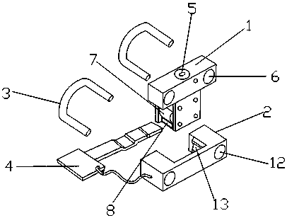
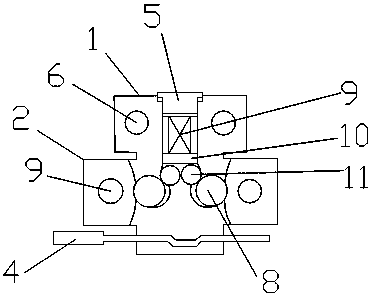
[0015] refer to Figure 1-2 As shown in the figure, a closely fitted mold clamp for injection molding includes a locking seat 1, a locking sleeve 2, a U-shaped fixing iron 3 and a safety bar 4, and the locking seat 1 is provided with an adjusting bolt 5, an upper The round hole 6, the card wheel 7 and the card groove 8, the adjustment bolt 5 and the card wheel 7 are all embedded in the locking seat, and a butterfly spring 9 is arranged below the adjustment bolt 5, and the butterfly spring 9 The bottom is provided with a top plate 10, and the bottom of the top plate 10 is provided with an internal roller 11, which is rollingly connected between the internal roller 11 and the card wheel 7, and a cavity (not shown) is provided between the card wheel 7 and the locking seat 1. As shown in the figure), the locking sleeve 2 is provided with a lower circular hole 12 and a semicircular groove 13, the semicircular groove 13 and the locking sleeve 2 are integrally formed, and the U-shape...


PUM


Abstract

The invention discloses a tightly fit injection mold locker which comprises a locking seat, a locking sleeve, U-shaped fixing irons and a safety strip, wherein an adjusting bolt, a clamping wheel, upper circular holes and a clamping groove are arranged and formed in the locking seat; the adjusting bolt and the clamping wheel are embedded into the locking seat; a belleville spring is arranged below the adjusting bolt; an ejection plate is arranged below the belleville spring; internal rolling wheels are arranged below the ejection plate; the internal rolling wheels are in rolling connection with the clamping wheel; a cavity is formed between the clamping wheel and the locking seat; the locking sleeve is provided with lower circular holes and semicircular grooves; the semicircular grooves and the locking sleeve are molded integrally; the U-shaped fixing iron is mounted in the upper circular holes and the lower circular holes; and the safety strip is mounted in the clamping groove.

Description

technical field [0001] The present invention relates to mold clamps, and more particularly, to a closely fitting mold clamp for injection molds. Background technique [0002] Injection molding is a processing method used in the mass production of certain complex-shaped parts. Specifically, it refers to injecting the heated and melted material into the mold cavity by high pressure, and after cooling and solidifying, a molded product is obtained. Injection mold is a tool for producing plastic products, and it is also a tool for giving plastic products complete structure and precise dimensions. Injection molds are usually composed of two parts: a movable mold and a fixed mold. The movable mold is installed on the movable template of the injection molding machine, and the fixed mold is installed on the fixed template of the injection molding machine. During injection molding, the movable mold and the fixed mold are closed to form the gating system and the cavity, and the movab...

Claims


Application Information

Patent Timeline
Patent Type & Authority Patents(China)
IPC IPC(8): B29C45/66
CPCB29C45/66B29C2045/664
Inventor 钟锋良陈萌
Owner 钟锋良
Why Eureka
Try Eureka