Hybrid type automobile electrophoresis coating conveying mechanism dynamics modeling method

A technology for dynamic modeling and conveying mechanism, applied in simulators, electrical digital data processing, program control, etc., can solve problems such as the same or similar methods that have not been seen, and achieve easy programmatic implementation and simple dynamic modeling methods. , the effect of neat form

Active Publication Date: 2015-12-16
JIANGSU UNIV
View PDF7 Cites 6 Cited by
  • Summary
  • Abstract
  • Description
  • Claims
  • Application Information

AI Technical Summary

Problems solved by technology

[0004] The method that the present invention proposes, through consulting bibliographic data, does not see that identical or similar method is reported to some extent

Method used


Image

  • Hybrid type automobile electrophoresis coating conveying mechanism dynamics modeling method
  • Hybrid type automobile electrophoresis coating conveying mechanism dynamics modeling method
  • Hybrid type automobile electrophoresis coating conveying mechanism dynamics modeling method

Examples


Embodiment

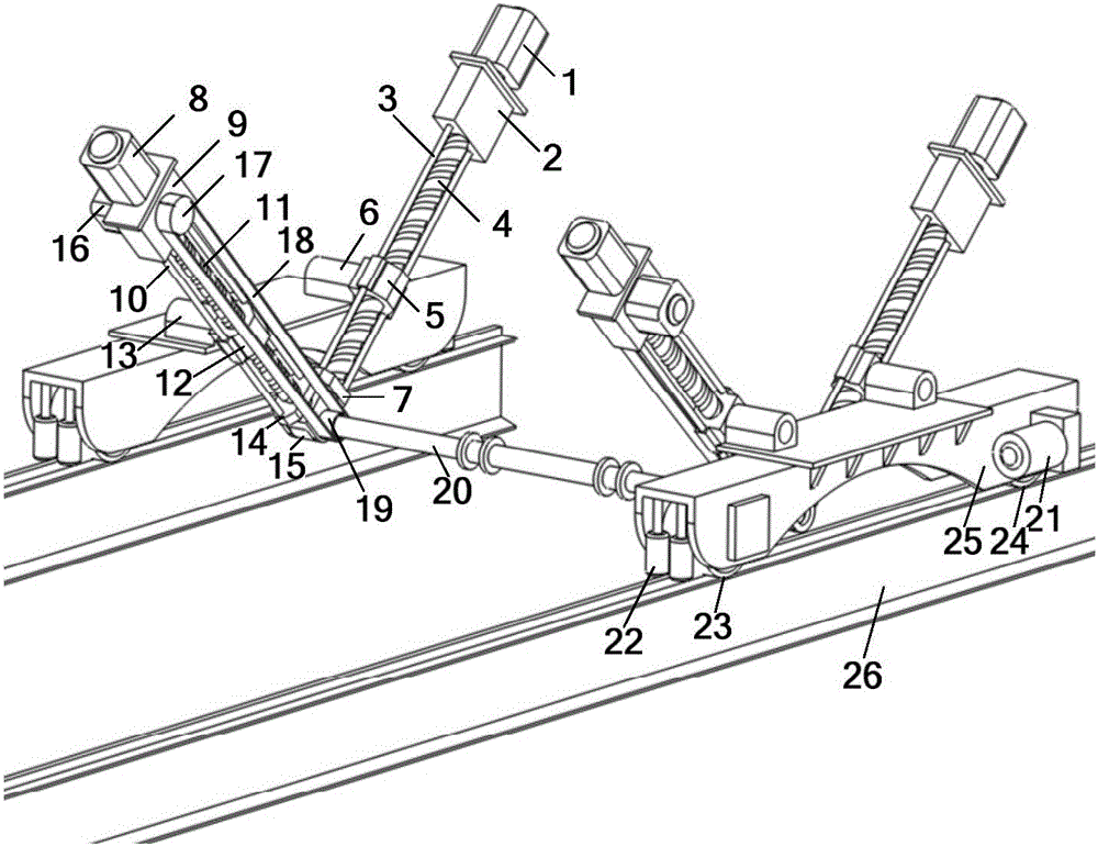
[0066] figure 1 The mechanism is a hybrid automobile electrophoretic coating conveying mechanism, which includes two functional parts: a walking mechanism and a lifting and turning mechanism. Wherein, the walking mechanism realizes the walking transportation function of the conveying mechanism through the cooperation of the walking driver 21, the guide wheel 22, the traveling wheel 23, the traveling wheel 24 and the guide rail 26. The frame of the lifting and turning mechanism is the moving part of the walking mechanism, and the lifting and turning mechanism is mainly composed of two groups of identical plane multi-rod mechanisms. The planar multi-bar mechanism includes three branches, wherein the first branch includes: the first driver 1, the first reducer 2, the first guide rail 3, the first lead screw 4, the first nut 5, the first rotating Auxiliary 6 and first screw seat 7; the first driver 1 is fixed on the first reducer 2, the first guide rail 3, the first screw seat 7 ...

specific Embodiment approach

[0070] The specific implementation of the modeling method of the present invention is as follows:

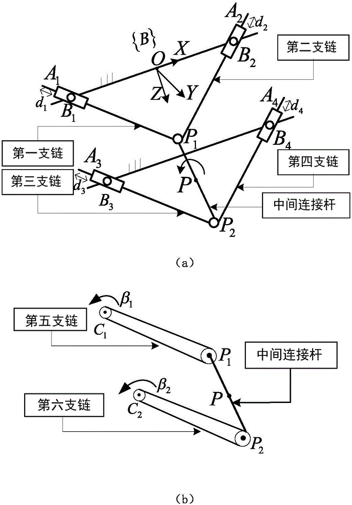
[0071] 1. If figure 2 As shown, the basic coordinate system {B}={O-XYZ} is established, and the origin O is located at B 1 and B 2 The midpoint of , the Z-axis is perpendicular to the base feature plane, and the Y-axis is along the P 1 P 2 Since the parallel mechanism actuation platform only has three degrees of freedom of movement along the X and Y directions and rotation around the Y axis, the pose parameter of the middle connecting rod is selected as q=[x, z, β] T (The units of x and z are m respectively, and the unit of β is rad).

[0072] Depend on figure 2 The analysis shows that the hinge point B between the nut and the base in the first, second, third, and fourth branch chains i (i=1, 2, 3, 4) coordinates in the basic coordinate system and the hinge point P between the two ends of the intermediate connecting rod and each branch chain i The coordinates of (i=1, 2...


PUM


Abstract

The invention discloses a hybrid type automobile electrophoresis coating conveying mechanism dynamics modeling method. First of all, the symmetrical structure characteristic of a mechanism is fully utilized, the speed and the accelerated speed of each passive joint in the mechanism are analyzed through an analytical geometry method, and then the speed and the accelerated speed of each active joint of the mechanism are obtained by introducing a screw theory; secondly, based on this, a kinetic equation in a mechanism spinor form is established by use of virtual work principle; and finally, axial driving power of each active joint of the conveying mechanism capable of directly realizing control is obtained through calculation so that construction of a dynamics model capable of realizing high-performance control is completed. According to the invention, the analytical geometry method, the screw theory and the virtual work principle are combined together, so that the problem of coordinate transformation due to lack of coordinate invariance during dynamics modeling of a complex special mechanism is solved, the calculation complexity is reduced, and at the same time, the dynamics modeling method brought forward by the invention is quite simple, is tidy in form and is easy in programmed realization.

Description

technical field [0001] The invention relates to a dynamic modeling method of a hybrid automobile electrophoresis coating conveying mechanism, which belongs to the field of hybrid / parallel robots. Background technique [0002] With the rapid development of the automobile manufacturing industry, automobile painting has developed from a workshop to a modern industrial painting suitable for mass flow production. In the painting process, the automobile body electrophoretic coating mechanized conveying system runs through the whole process of the automobile painting production line, and is the main artery of the painting production line. At present, a new hybrid automobile electrophoretic coating conveying mechanism has been proposed. The hybrid automotive electrophoretic coating conveying mechanism has the advantages of both parallel mechanism and series mechanism. It not only has a large rigidity-to-weight ratio, small cumulative error, compact structure, strong bearing capacit...

Claims


Application Information

Patent Timeline
Patent Type & Authority Applications(China)
IPC IPC(8): G05B17/02G06F17/50
CPCG05B17/02G05B2219/33257G05B2219/33263G06F30/20
Inventor 高国琴陈太平
Owner JIANGSU UNIV
Why Eureka
Try Eureka