A miniaturized dielectric phase shifter

A phase shifter and dielectric technology, which is applied in waveguide devices, electrical components, circuits, etc., can solve the problems of unstable performance, small phase shift amount, and high cost of dielectric boards, and achieve the reduction of nonlinear electrical connection points and large output Phase delay, easy to process and manufacture effects

Active Publication Date: 2018-03-02
ANHUI SUN CREATE ELECTRONICS
View PDF4 Cites 0 Cited by
  • Summary
  • Abstract
  • Description
  • Claims
  • Application Information

AI Technical Summary

Problems solved by technology

[0003] At present, the phase shifter mainly changes its phase in two ways, one is by changing the physical length of signal transmission, the part of the transmission line with variable physical length is generally printed on the pcb board, and the coupling method is often used to connect with the main feeder line, as in the patent 03815422.6, this method has high requirements on the smoothness of the printed board, and the slack of the circuit board will change the coupling, thereby affecting the standing wave ratio and power division ratio of the phase shifter, and the performance is unstable
[0004] The other is to change the equivalent power-saving constant. This method usually uses the moving dielectric plate near the feeder to change the area of ​​the dielectric plate covering the feeder, thereby changing the equivalent power-saving constant and making the signal output different phases, such as patent 201020148882.3, The transmission line part of this phase shifter adopts a strip line structure, and the central metal feeder part is mostly a linear structure, which is large in size and complex in structure, and is not suitable for large-scale processing. Due to the high cost of the dielectric plate with high dielectric constant, the actual Most of them use dielectric plates with low dielectric constants, which can achieve small phase shifts

Method used


Image

  • A miniaturized dielectric phase shifter
  • A miniaturized dielectric phase shifter
  • A miniaturized dielectric phase shifter

Examples


Embodiment 1

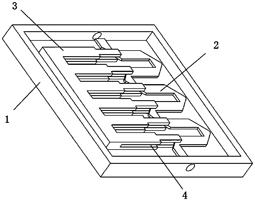
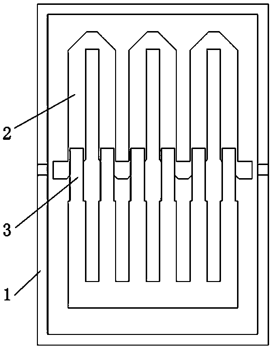
[0038] see figure 2 , further speaking, a transmission line 2 and a dielectric block 3 are arranged in the box body 1 . The longitudinal section of the dielectric block 3 that contains a side groove 4 is U-shaped, such as Figure 4 shown.

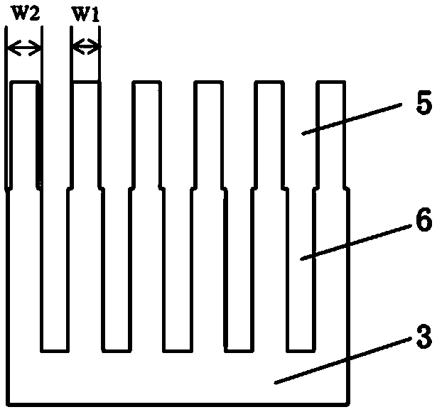
[0039] see image 3 , more than one first-level opening 5 is provided on the top edge of the dielectric block 3 on the side close to the transmission line 2 . A second-stage opening 6 is provided on the dielectric block 3 on one side of the closed end of each first-stage opening 5 . That is, the edge of the top surface of the dielectric block 3 is a stepped protrusion, and the stepped protrusion extends toward the direction of the transmission line 2 .

[0040] The width of the first stage opening 5 is greater than the width of the second stage opening 6 .

[0041] When the dielectric block 3 with the first-level opening 5 and the second-level opening 6 is displaced relative to the transmission line 2, the dielectric area covered on t...

Embodiment 2

[0047] see Figure 6 , further speaking, a transmission line 2 and a dielectric block 3 are arranged in the box body 1 . The longitudinal section of the dielectric block 3 with one side groove 4 is U-shaped.

[0048] More than one set of through-hole groups 7 is provided on the top edge of the dielectric block 3 on the side close to the transmission line 2 .

[0049] The through hole group 7 includes two or more circular holes. The radius of the circular holes in each group of through hole groups 7 gradually increases from the inside to the outside. The distance between two adjacent groups of through hole groups 7 is between 1 mm and 3 mm.

[0050] In this structure, by changing the size of the circular hole, the area of ​​the dielectric block 3 covering the transmission line 2 is changed, thereby changing the equivalent energy-saving constant of the corresponding position, and then changing the characteristic impedance of the transmission line, finally realizing impedance ...

Embodiment 3

[0056] see Figure 7 , further speaking, two transmission lines 2 and a dielectric block 3 are arranged in the box body 1 . The longitudinal section of the dielectric block 3 containing two side grooves 4 is H-shaped, such as Figure 9 shown.

[0057] see Figure 8 The top edges of the two ends of the dielectric block 3 close to the transmission line 2 are respectively provided with more than one first-level opening 5 . A second-stage opening 6 is provided on the dielectric block 3 on one side of the closed end of each first-stage opening 5 . That is, the top surface of the dielectric block 3 is approximately in the shape of a "thirty".

[0058] Moving the position of the dielectric block 3 relative to the transmission line 2, the covered area of ​​the upper transmission line 2 becomes larger, and the equivalent power-saving constant becomes larger, and the phase change of the output port of the upper transmission line 2 is -Δ. At the same time, The covered area of ​​the ...


PUM


Abstract

The invention relates to a miniaturized dielectric phase shifter which comprises a box body, a cover plate, a transmission line, a dielectric block and a slide mechanism. The box body is a hollow rectangular block with one open end. The cover plate is arranged on the open part of the box body in a matching way. The outer side of the cover plate is provided with the slide mechanism and a slide hole. The transmission line and the dielectric block are arranged inside the chamber of the box body. The transmission line is connected with the box body inner wall in an insulating way. After passing through the slide hole on the cover plate, the dielectric block is connected with the external slide mechanism. The dielectric block side surface adjacent to the transmission line is provided with a side surface groove. The central part of the transmission line passes through the side surface groove of the dielectric block. The transmission line and the dielectric block do not contact each other. The miniaturized dielectric phase shifter with a small volume is especially suitably used in a base station tunable antenna with a limited space. Furthermore, the phase shifter with a simple structure is easy to process and manufacture and has the characteristics of continuous phase changes, good cross modulation characteristics and great phase shift quantity.

Description

technical field [0001] The invention relates to the fields of mobile communication base station antennas and radio frequencies, in particular to a miniaturized dielectric phase shifter applied to electrically adjustable base station antennas. Background technique [0002] At present, the electric adjustment base station antenna has been widely used in China's cities and rural areas, and the electric adjustment of the base station antenna mainly relies on the phase shifter to change the feeding phase of each antenna unit in the antenna array, so as to realize the downtilt of the main beam of the antenna. That is, the ESC is tilted down. [0003] At present, the phase shifter mainly changes its phase in two ways, one is by changing the physical length of the signal transmission, the transmission line part with variable physical length is generally printed on the pcb board, and the coupling method is mostly used to connect with the main feeder line, as in the patent 03815422.6...

Claims


Application Information

Patent Timeline
Patent Type & Authority Patents(China)
IPC IPC(8): H01P1/18H01Q3/32
Inventor 季宏红朱小三夏义全胡卫东赵继明
Owner ANHUI SUN CREATE ELECTRONICS
Why Eureka
Try Eureka