Automatic turning material frame device for cleaning valve lifters

A valve lifter and automatic flipping technology, which is applied to cleaning methods and appliances, cleaning methods using liquids, chemical instruments and methods, etc., can solve the problem of workpiece position restrictions, workpieces that cannot meet cleaning requirements, workpieces that are blown away or blown away. Flying and other problems, to achieve a good cleaning effect

Active Publication Date: 2017-05-03
SICHUAN UNIV
View PDF12 Cites 0 Cited by
  • Summary
  • Abstract
  • Description
  • Claims
  • Application Information

AI Technical Summary

Problems solved by technology

[0003] Nowadays, offline cleaning equipment with ultrasonic spraying function modules is generally used for cleaning valve lifters. When cleaning, place the workpiece with the opening facing down behind the material frame, and drag the entire material frame slowly into the ultrasonic cleaning equipment by the manipulator. Cleaning, the workpiece is still relative to the material frame after it is put into the material frame. When the workpiece is immersed in the cleaning liquid, because the air in the cavity is not removed, the cleaning liquid cannot completely fill the inner cavity of the workpiece, the ultrasonic effect cannot be fully exerted, and the workpiece cannot reach cleaning requirements
Moreover, for some lighter workpieces, due to the impact of high-pressure liquid during spray cleaning, the regularly placed workpieces will be blown away or blown away, which cannot play a good role in restricting the position of the workpieces.

Method used


Image

  • Automatic turning material frame device for cleaning valve lifters
  • Automatic turning material frame device for cleaning valve lifters
  • Automatic turning material frame device for cleaning valve lifters

Examples


Embodiment Construction

[0011] The present invention is specifically described below by examples, it is necessary to point out that the following examples are only used to further illustrate the present invention, and can not be interpreted as limiting the protection scope of the present invention, those skilled in the art can understand the present invention according to the contents of the present invention Invention to make some non-essential improvements and adjustments.

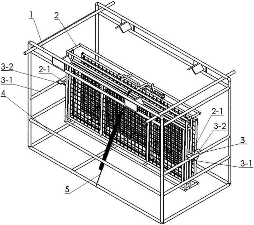
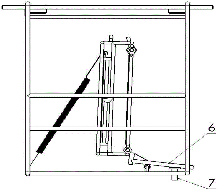
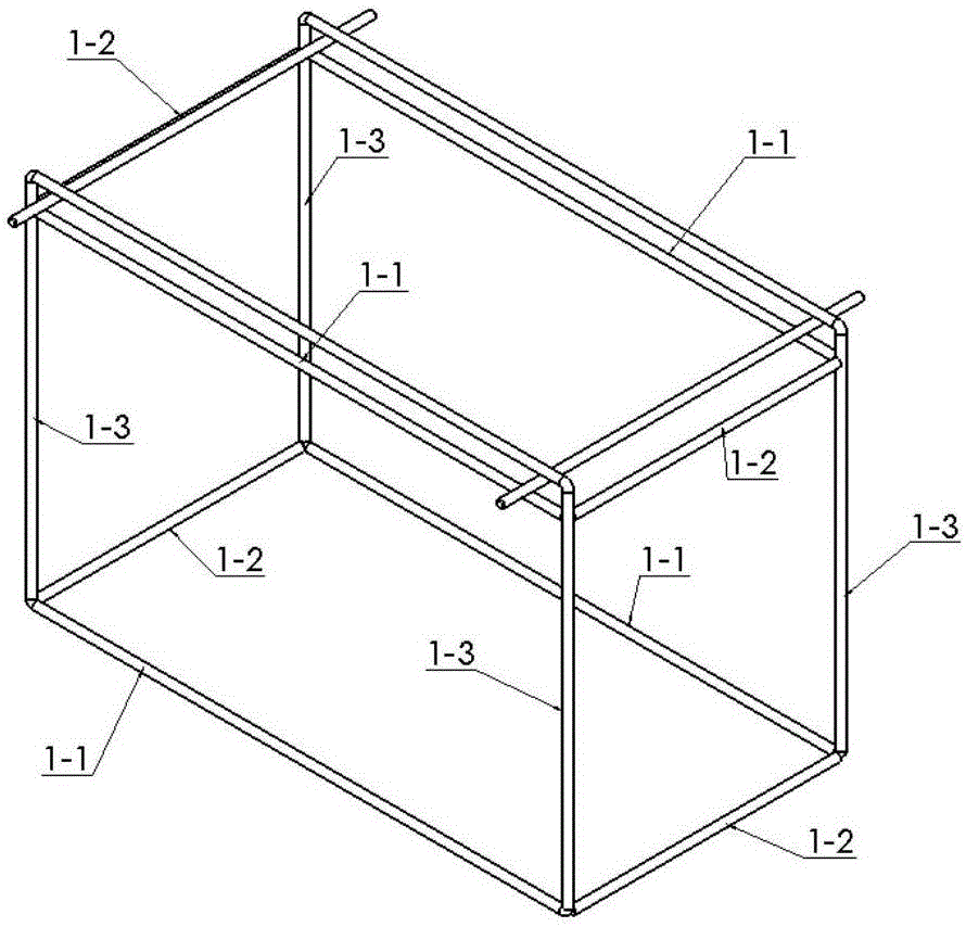
[0012] Such as figure 1 and figure 2 The shown automatic flip material frame device for ultrasonically cleaning valve lifters includes a material frame 1, a material frame 2, a support device 3, a horizontal frame 4, a spring 5, a ejector rod device 6 and a thimble 7, and the material frame 1 is A cuboid frame welded by the first round steel 1-1, the second round steel 1-2 and the third round steel 1-3 three groups of round steel, the support device 3 is composed of a bearing rod 3-1 and a support plate 3-2, the load-bearing...


PUM


Abstract

The invention relates to a material frame device for ultrasonic cleaning of a valve lifter. The material frame device comprises a material framework (1), a material frame (2), a supporting device (3), a horizontal frame (4), a spring (5), an ejector rod device (6) and an ejector pin (7). The material frame (2) is arranged on the material framework (1) in a lap joint manner through the supporting device (3) and keeps vertical under the effect of the spring (5) and the ejector rod (6). When the material framework (1) is completely immersed in cleaning fluid, the ejector rod (6) acts with the ejector pin (7) to be separated from the material frame (2) and does not make contact with the material frame (2), and the material frame (2) overturns automatically and makes contact with the horizontal frame (5) to be horizontal. Due to the fact that the material frame can overturn automatically, the cleaning fluid can completely enter an inner cavity of the valve lifter, then impurities and oil dirt in an inner cavity hole can be effectively cleaned away, and the cleaning effect is greatly improved.

Description

[0001] Technical field [0002] The patent of the present invention relates to a device that can automatically turn over the material frame, in particular to the cleaning of cup-shaped industrial parts containing blind holes in inner cavities, such as valve lifters. Background technique [0003] Nowadays, offline cleaning equipment with ultrasonic spraying function modules is generally used for cleaning valve lifters. When cleaning, place the workpiece with the opening facing down behind the material frame, and drag the entire material frame slowly into the ultrasonic cleaning equipment by the manipulator. Cleaning, the workpiece is still relative to the material frame after it is put into the material frame. When the workpiece is immersed in the cleaning liquid, because the air in the cavity is not removed, the cleaning liquid cannot completely fill the inner cavity of the workpiece, the ultrasonic effect cannot be fully exerted, and the workpiece cannot reach cleaning requir...

Claims


Application Information

Patent Timeline
Patent Type & Authority Patents(China)
IPC IPC(8): B08B3/12
CPCB08B3/048B08B3/12
Inventor 傅波田鹏王文亚岳祺宇罗经平庄文敏傅一恒
Owner SICHUAN UNIV
Why Eureka
Try Eureka