Horizontal large nut erector

A large nut and installer technology, which is applied in metal processing, metal processing equipment, manufacturing tools, etc., can solve problems such as jamming, difficulty in installing and rotating large nuts, and difficulty in installing nuts, so as to solve the problem of increased friction and large The effect of the one-sided force problem on the nut

Active Publication Date: 2015-12-23
KEDA INDUSTRIAL GROUP CO LTD
View PDF6 Cites 2 Cited by
  • Summary
  • Abstract
  • Description
  • Claims
  • Application Information

AI Technical Summary

Problems solved by technology

[0002] In the process of installation and maintenance of industrial equipment, when installing nuts or screws, the most feared thing is that the surface of the thread will be strained, because the thread will produce a small amount of iron cutting after the thread is strained, and the iron cutting will grind more and more, just like a snowball In that way, the nut is screwed tighter and tighter, and cannot be screwed out or screwed in, and finally leads to "stuck" phenomenon
At this time, it will be very difficult to remove the nut (especially a large nut), and even the part will eventually be scrapped
[0003] Large nuts are much more difficult to install than small and medium-sized nuts. In addition to the fact that large nuts are relatively bulky, when the hardness of the thread surface is constant, the heavier the nut, the greater the friction when rotating, and the easier it is to damage the thread surface. finish, and eventually strain the threads; at the same time, high friction can make it very difficult for large nuts to be installed and rotated
In addition, the horizontal installation of large nuts is much more difficult than the vertical installation. The main reason is: due to the gravity factor, when the horizontal nut is installed, the force is mainly on the upper side, so the friction generated when the nut is rotated is greater. , more likely to strain the threaded surface

Method used


Image

  • Horizontal large nut erector
  • Horizontal large nut erector
  • Horizontal large nut erector

Examples


Embodiment Construction

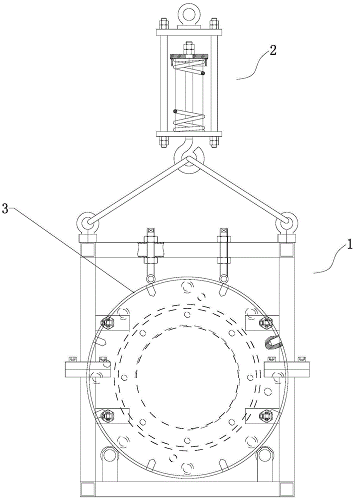
[0023] Such as figure 1 and figure 2 As shown, the horizontal large nut installer of the present invention consists of a rotator 1 and a buffer 2.

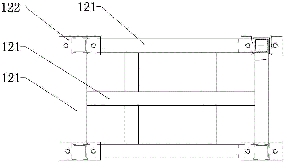
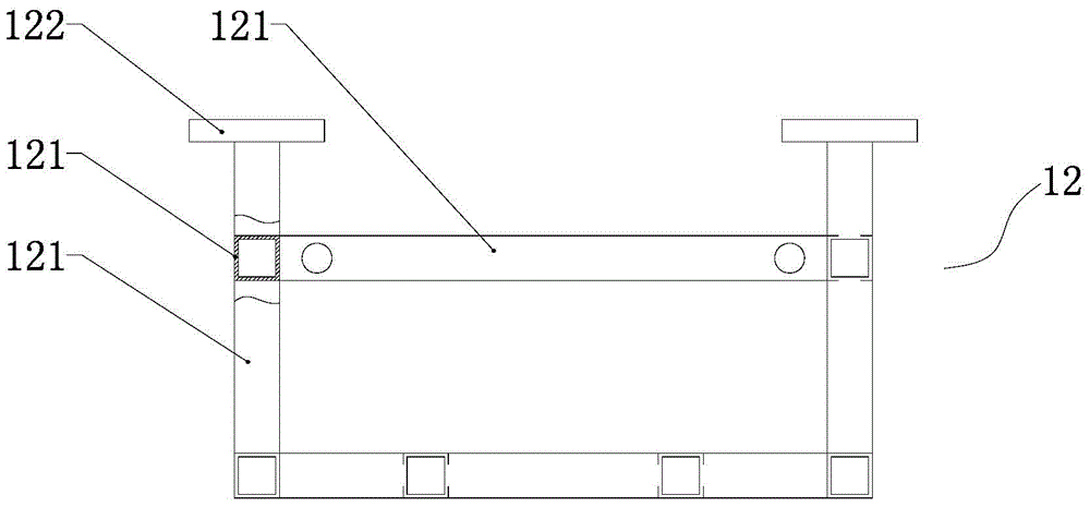
[0024] The rotator 1 is mainly composed of a support frame in the shape of a cuboid and a plurality of bearings 13 arranged on the frame. The support frame is movably connected by an upper support frame 11 and a lower support frame 12 . Wherein, the lower supporting frame 12 is mainly a rectangular parallelepiped frame formed by a plurality of square tubes 121 , and a connecting plate 121 is respectively fixed to the ends of the square tubes on four sides. The structure of the upper supporting frame 11 is the same as that of the lower supporting frame, and two hanging rods 111 are provided on its upper end surface. The upper support frame 11 and the lower support frame 12 constitute the whole support frame through the joining of the connecting plates on four sides, and form a placement area for placing large nuts in the suppor...


PUM


Abstract

The invention discloses a horizontal large nut erector. The horizontal large nut erector comprises a rotator and a buffer. The rotator is used for a large nut to be fixed in the rotator, and the large nut can freely rotate around the central axis of the large nut. The buffer is used for the rotator to hang below. The rotator is mainly formed by an upper bearer frame, a lower bearer frame, and a plurality of bearings. The buffer is mainly formed by an installation frame, a hook, and an elastic assembly. The rotator can make a large nut rotate freely in a vertical and stable manner in the rotator, and the buffer can make threads stress uniformly when the large nut is installed, and finally, screw-out and screw-in operation of the large nut are easily realized, and the threads cannot easily be scratched. The horizontal large nut erector effectively solves problems of increasing of friction forces and single-side stress of the large nut caused by gravity of the nut when the large nut is installed in a horizontal manner.

Description

technical field [0001] The invention relates to a large nut installation auxiliary device, in particular to a horizontal large nut installer. Background technique [0002] In the process of installation and maintenance of industrial equipment, when installing nuts or screws, the most feared thing is that the surface of the thread will be strained, because the thread will produce a small amount of iron cutting after the thread is strained, and the iron cutting will grind more and more, just like a snowball In that way, the nut is screwed tighter and tighter, and cannot be screwed out or screwed in, which eventually leads to a "stuck" phenomenon. At this time, it will be very difficult to remove the nut (especially the large nut), and even the part will eventually be scrapped. [0003] Large nuts are much more difficult to install than small and medium-sized nuts. In addition to the fact that large nuts are relatively bulky, when the hardness of the thread surface is constant...

Claims


Application Information

Patent Timeline
Patent Type & Authority Applications(China)
IPC IPC(8): B23P19/06
Inventor 杜志远杨晓光
Owner KEDA INDUSTRIAL GROUP CO LTD
Why Eureka
Try Eureka