Wire clamping mechanism suitable for ultra-thin line spring wire

An ultra-fine wire and spring wire technology, applied in workpiece clamping devices, manufacturing tools, etc., can solve the problems of being pulled, affecting the quality and efficiency of wire feeding, discounting, etc. , the effect of reducing friction

Active Publication Date: 2018-02-02
上海坤链连接器有限公司
View PDF5 Cites 0 Cited by
  • Summary
  • Abstract
  • Description
  • Claims
  • Application Information

AI Technical Summary

Problems solved by technology

Because in the above-mentioned clamping wire mechanism, each wire spring wire is respectively pressed by the down pressure of a wire pressing plate, the radial tolerance and axial straightness of the wire spring wire and the wear and tear of the length of the wire pressing plate result in many It is difficult to balance and synchronize the compressive force between the spring wires of the wires, and it is easy to cause some wire spring wires to not be clamped tightly, which will affect the quality and efficiency of subsequent wire feeding
In particular, with the development of modern high-precision technology, the diameter of the wire spring wire used in the wire spring hole has an ultra-fine specification of 0.08mm and below. If this ultra-fine wire spring wire adopts the above-mentioned existing wire

Method used


Image

  • Wire clamping mechanism suitable for ultra-thin line spring wire
  • Wire clamping mechanism suitable for ultra-thin line spring wire
  • Wire clamping mechanism suitable for ultra-thin line spring wire

Examples


Embodiment

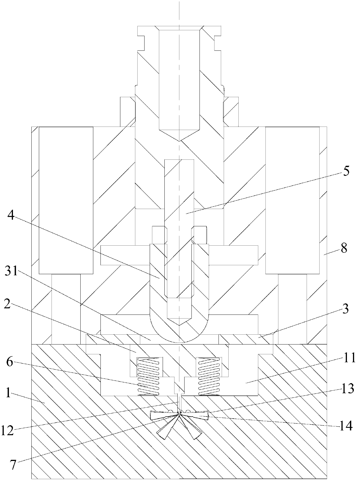
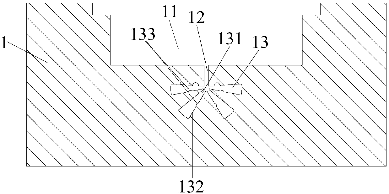
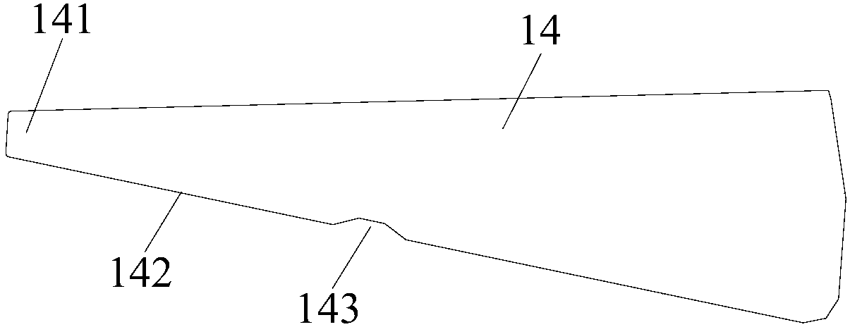
[0030] Please combine Figure 1 to Figure 8 As shown, this embodiment provides a clamping mechanism applicable to ultra-fine wire spring wire, including a base 1, a wire pressing member 2, a limiting member 3, a pressing member 4 and a power output member 5, the base 1 is provided with an opening groove 11 at the center, and an opening slot 12 is arranged at the center of the base below the opening groove 11, and the opening slot 12 communicates with the opening groove 11. The base below the slot 12 is provided with a plurality of cavities 13 centered on the lower end of the opening slot 12, uniformly radially distributed around, and left and right to form a center symmetry (the present embodiment takes 4 as an example, but Not limited to this), each cavity 13 is respectively provided with a movable piece 14 matching its respective shape, and each movable piece 14 has a movable gap in its corresponding cavity 13 and extends out of the cavity; The wire pressing part 2 is T-shape...


PUM


Abstract

The invention discloses a wire clamping mechanism suitable for an ultra-thin line spring wire. The wire clamping mechanism comprises a base, a wire pressing piece, a limiting piece, an abutting pieceand a power output piece; the center of the base is provided with an opening groove and an opening insertion groove communicated with the opening groove, a plurality of cavities are formed below the opening insertion groove, a movable piece matched with each cavity in shape is arranged in each cavity, and each movable piece has a movement gap in the cavity corresponding to the movable piece and extends out of the cavity; and the wire pressing piece is in a T type, a wire pressing part is arranged at the lower portion and is inserted into the opening insertion groove, and the line spring wiresare arranged in gap formed by the wire pressing part and the movable pieces adjacent to the wire pressing part and gap formed between every two adjacent movable pieces in a penetrating manner. The power output piece drives the descending motion of the abutting piece, the wire pressing part can move downwards, the pressure is sequentially transmitted, and a closed pressure equivalent transmitting ring is formed, the line spring wire bears the balance pressure and is clamped synchronously, and clamping of the ultra-thin line spring wires can be achieved.

Description

technical field [0001] The invention relates to a wire clamping mechanism for wire spring wire, in particular to a wire clamping mechanism applicable to ultra-thin wire spring wire (wire spring wire with a diameter of 0.08mm and below), which belongs to wire spring Hole automatic assembly technology field. Background technique [0002] The wire spring hole is a highly reliable socket component on the electrical connector product, which is composed of an inner sleeve, an outer sleeve and multiple wire spring wires. When the pin is inserted into the wire spring hole, the wire spring wire is elastically deformed in the radial direction and the axial direction, and the pin is in contact with multiple independent wire spring wires in the wire spring hole at the same time, forming multiple independent current paths. It has many advantages such as low and stable contact resistance, small plugging force, low contact wear, long plugging life, and high reliability of electrical conta...

Claims


Application Information

Patent Timeline
IPC IPC(8): B25B11/02
CPCB25B11/02
Inventor 陈旭浦王锦涛
Owner 上海坤链连接器有限公司
Why Eureka
Try Eureka