Cylindrical grinding double top clamping tool

A double-top and cylindrical grinding technology, which is applied in the direction of grinding workpiece supports, grinding drive devices, manufacturing tools, etc., can solve the problem of shaking during the sliding process of the carriage, increased shaking of the top, and increased coaxiality of the product, etc. problem, to achieve the effect of reducing the shaking gap, low manufacturing cost and simple structure

Active Publication Date: 2018-03-16
NINGBO YUNSHENG BONDED MAGNET CO LTD
View PDF7 Cites 0 Cited by
  • Summary
  • Abstract
  • Description
  • Claims
  • Application Information

AI Technical Summary

Problems solved by technology

[0002] At present, the top device for coaxial processing of fiber optic ceramic ferrules generally uses a miniature linear guide rail to mount a carriage to realize the movement of the top, and the distance between the top and the guide rail is generally about 50 mm (this includes the thickness of the carriage and the height of the top seat) , because there is a gap in the linear guide rail, there will be shaking during the sliding process of the carriage, and the top of the carriage will enlarge the gap because it is 50mm away from the guide rail, which will increase the shaking of the top and cause the coaxiality of the processed product to become larger

Method used


Image

  • Cylindrical grinding double top clamping tool
  • Cylindrical grinding double top clamping tool
  • Cylindrical grinding double top clamping tool

Examples


Embodiment Construction

[0016] The present invention will be further described below in conjunction with drawings and embodiments.

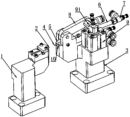
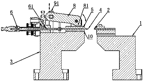
[0017] Such as figure 1 The cylindrical grinding double-top clamping tool shown includes left base 1, left top 2, right base 3, right top 4, pressing block 5, jacking cylinder 6, air pressure regulating valve 7, rocker arm 8, pressing Cylinder 9, guide block 10.

[0018] The position of the left base 1 is fixed, and the left top 2 is fixed on the left base 1. The position of the right base 3 is fixed, and the right top 4 is installed on the left base 3, and the tops of the two tops on the left and right are relative and coaxial.

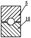
[0019] The device mode of right top 4 is as follows figure 1 , figure 2 As shown: the guide block 10 is fixed on the right base 3, the guide block 10 is provided with a guide groove, the guide groove is in the same direction as the left top, the right top 4 is located in the guide groove, the compression block 5 is fastened above the rig...


PUM


Abstract

The invention discloses a cylindrical grinding double-tip clamping tool. The tool comprises a left base, a right base, a left tip, a right tip, a tip driving mechanism, a pressing block and a pressing device. The two tips are coaxial, and the tops of the tips are opposite to each other. The left tip is fixed to the left base. A guide groove is formed in the right base or the pressing block. The right tip is located in the guide groove. The pressing block can be in contact with the right tip. The tip driving mechanism drives the right tip to move along the guide groove. The pressing device drives the pressing block to squeeze or release the right tip. Preferably, the tip driving mechanism is an ejection air cylinder. The ejection air cylinder is provided with an air pressure adjusting valve. Preferably, the pressing device comprises a pressing air cylinder and a swing arm. The pressing air cylinder drives an air cylinder connecting rod. One end of the swing arm is hinged to the air cylinder connecting rod, and the other end of the swing arm is provided with a cam and hinged to the right base. The air cylinder connecting rod moves up and down to drive the cam to rotate, and the pressing block below the cam is squeezed or released during rotation. When the tool is used for machining ceramic ferrules, shaking of the tips is reduced, and the coaxiality of ceramic ferrules is guaranteed.

Description

technical field [0001] The invention relates to a ceramic ferrule processing device, in particular to a tool for ensuring the coaxiality of the ceramic ferrule during processing. Background technique [0002] At present, the top device for coaxial processing of fiber optic ceramic ferrules generally uses a miniature linear guide rail to mount a carriage to realize the movement of the top, and the distance between the top and the guide rail is generally about 50 mm (this includes the thickness of the carriage and the height of the top seat) , because there is a gap in the linear guide rail, the carriage will shake during the sliding process, and the top of the carriage will enlarge the gap because it is 50 mm away from the guide rail, which will increase the shaking of the top and cause the coaxiality of the processed product to increase. Therefore, it is necessary to design a device to reduce the shaking of the tip, thereby improving the coaxiality of the fiber optic ceramic...

Claims


Application Information

Patent Timeline
Patent Type & Authority Patents(China)
IPC IPC(8): B24B41/06B24B47/14
CPCB24B41/062B24B47/14
Inventor 钱定权郑争忻元超
Owner NINGBO YUNSHENG BONDED MAGNET CO LTD
Why Eureka
Try Eureka