Filter used for prilling through paper making waste residues

A papermaking waste residue and filter technology, applied in the field of papermaking, can solve the problems of increasing labor intensity of workers, frequent screen changing steps, reducing production efficiency, etc., so as to save removal and installation steps, avoid heat loss and waste, and ensure production efficiency. Effect

Active Publication Date: 2015-12-23
烟台大为环保科技有限公司
View PDF7 Cites 1 Cited by
  • Summary
  • Abstract
  • Description
  • Claims
  • Application Information

AI Technical Summary

Problems solved by technology

[0008] The first is the loss of energy, reciprocating and alternately replacing the wire mesh 6, the process of changing the wire mesh 6 is to push the wire mesh device 2 in the filter housing 1 out of the housing 1, which will inevitably bring out a large amount of heat in the housing 1 The outside of the casing 1 first causes the loss of this part of the heat, and more importantly, the new wire mesh device 2 enters the casing 1, because the temperature outside the casing 1 is much lower than the plasticizing temperature inside the casing 1. Therefore, when the new screen device 2 enters the casing 1 and comes into contact with the hot plasticizing fluid, the part of the plasticizing fluid in contact with the screen device 2 will cool down rapidly, and the flow performance will drop sharply. Even solidification occurs, so that when the new screen 6 is used, there may also be a situation where the clean plasticizing fluid cannot be squeezed out smoothly. At this time, it is necessary to wait for other parts of the plasticizing fluid to melt the solidified plasticizing fluid. Only then can the normal filtering work be started; or, take out the screen device 2 to preheat and then put it into the casing 1, the whole operation is complicated, which not only greatly increases the labor intensity of the workers, but also delays the entire production process, Reduced production efficiency;
[0009] Secondly, the screen changing step is carried out frequently. During the screen changing process, the wire mesh filter is in a shutdown state, which directly reduces the production efficiency;
[0010] On the other hand, due to the hot state of the plasticizing fluid, there is a danger of scalding the operator during the replacement of the screen; moreover, during the replacement of the screen, smoke will be brought out, polluting the working environment, and affecting the operation. health hazard

Method used


Image

  • Filter used for prilling through paper making waste residues
  • Filter used for prilling through paper making waste residues
  • Filter used for prilling through paper making waste residues

Examples


Embodiment 1

[0048] Example 1, such as figure 2 , 3, 4 show:

[0049] A filter comprising:

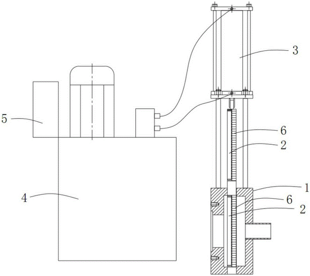
[0050] -Case 1, which has a cavity 2, a feed port 3, a discharge port 4 and a slag discharge port 5, and the papermaking waste is plasticized by a granulator to form a plasticized filter to be filtered Fluid, the plasticized fluid to be filtered enters the cavity 2 through the feed port 3, flows out from the discharge port 4 after being filtered, and the impurities in the plasticized fluid are discharged through the slag discharge port 5 ;

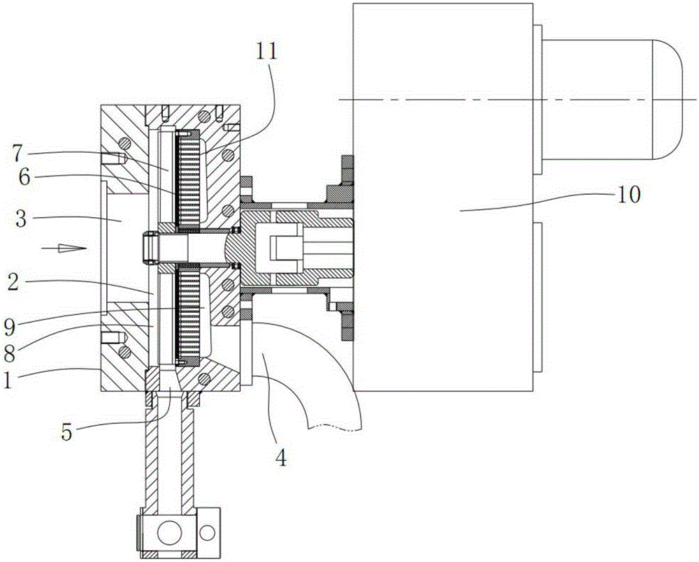
[0051] - microporous plate 6, said microporous plate 6 is provided with several through holes at intervals, said microporous plate 6 is arranged in said cavity 2, and said cavity 2 is divided into feeding cavity 8 and outlet Material chamber 9, when the plasticizing fluid passes through the microporous plate 6, the impurities in the plastic fluid are blocked on the side of the microporous plate 6 located at the feeding chamber 8;

[0052] - scraper 7, said...

Embodiment 2

[0055] Example 2, such as figure 2 , as shown in 3 and 4,

[0056] As described in Embodiment 1, a support plate 11 for supporting the microporous plate 6 is also provided in the discharge chamber 9, and the through holes on the microporous plate 6 extend toward the support plate 11, and Through the support plate 11, the side of the microporous plate 6 located in the feed chamber 8 is circular, the edge of the microporous plate 6 matches the side wall of the cavity 2, and the row The slag port 5 is arranged on the side wall of the cavity 2. When the driving device 10 drives the scraper 7, the scraper 7 rotates, and the rotation plane of the scraper 7 is located parallel to the microporous plate 6. On the side of the feeding chamber 8 , the outer edge of the scraper 7 matches the side wall of the feeding chamber 8 , and the slag discharge port 5 is arranged on the side wall below the chamber body 2 .

[0057] The plasticized fluid enters the discharge chamber 9 through the m...

Embodiment 3

[0058] Example 3, such as figure 2 , as shown in 3 and 4,

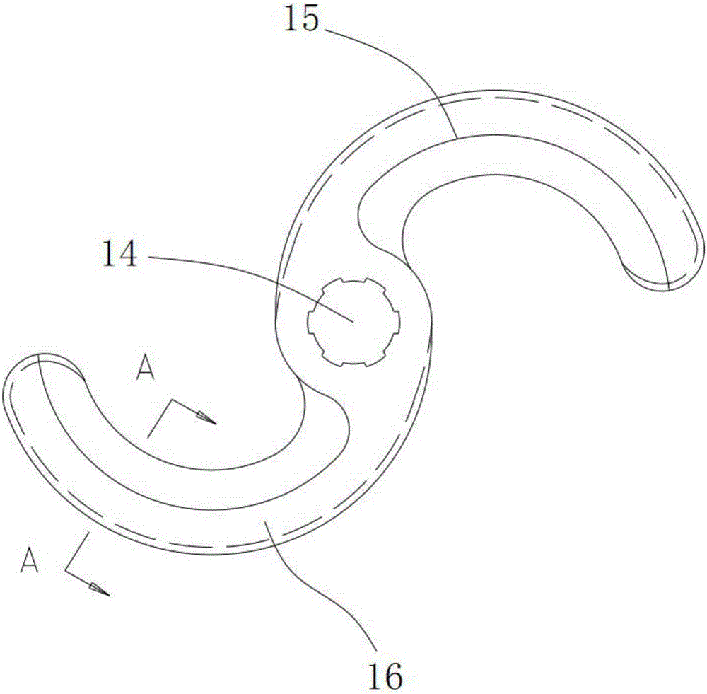
[0059] As described in Embodiment 1, the scraper 7 includes a knife body 12 and a knife edge 13 arranged on the knife body 12, and the knife edge 13 is located on the side of the microporous plate 6 in the feeding chamber 8 In cooperation, the cutter body 12 includes a mounting seat 14 for connecting with the driving device 10, and a first arc segment 15 and a second arc segment 16 are arranged on the mounting seat 14 apart from each other. The protruding direction of the arc segment 15 and the second arc segment 16 is consistent with the direction of rotation of the cutter body 12, and the blade 13 is made of cemented carbide. When the driving device 10 drives the scraper 7 to rotate, it faces The side of the impurity is the front side, and the side away from the impurity is the rear side. The blade 13 is arranged on the front side of the knife body 12, and the front side and the rear side of the knife body 12 are ...


PUM


Abstract

The invention relates to the technical field of paper making, in particular to a filter used for prilling through paper making waste residues. The filter comprises a filter shell, a microwell plate, a scraper and a driving device. The filter shell is provided with a cavity, a feeding port, a discharging port and a residue discharging port. When plastified liquid penetrates through the microwell plate, impurities in the plastified liquid are blocked on the side face, located in a feeding cavity, of the microwell plate. The scraper is arranged inside the feeding cavity. The scraper is matched with the side face of the microwell plate. The driving device drives the scraper to move along the side face of the microwell plate. When the scraper moves, the impurities adsorbed on the microwell plate are pushed to the residue discharging port. According to the scheme, the filter does not need to be stopped during the residue scraping process of the scraper, and the production efficiency is greatly improved.

Description

technical field [0001] The invention relates to the technical field of papermaking, in particular to a filter for granulating papermaking waste residue. Background technique [0002] With the strengthening of people's awareness of environmental protection and the country's emphasis on environmental protection, it is no longer feasible to use various production waste residues to landfill or incinerate. The harmless treatment of production waste residues has become a very urgent problem. At present, various waste residues The processing lines have been in operation one after another, while the processing line for papermaking waste is still in its infancy. [0003] The main component of papermaking waste is plastic skin. The essence of the current treatment of papermaking waste is the recycling of waste plastic skin. The current general process is to sequentially crush, separate, clean, rinse, dehydrate, dry, and make papermaking waste. Granulation and other processes, so that...

Claims


Application Information

Patent Timeline
Patent Type & Authority Applications(China)
IPC IPC(8): B29C47/68B29B9/06
CPCB29B9/06B29C48/69
Inventor 丁延莉郑冰刘耀祖王庆军
Owner 烟台大为环保科技有限公司
Why Eureka
Try Eureka