Mobile catenary for electrified railway coaling station

A technology of electrified railway and catenary, applied in the direction of power lines, transportation and packaging, overhead lines, etc., can solve the problems of restricting the efficiency of logistics chain, inability to erect flexible catenary, space occupation, etc., and achieve infinitely adjustable size and high rigidity , the effect of beautiful structure

Active Publication Date: 2015-12-23
CHINA RAILWAY HIGH SPEED ELECTRIFICATION EQUIP CORP LTD
View PDF7 Cites 4 Cited by
  • Summary
  • Abstract
  • Description
  • Claims
  • Application Information

AI Technical Summary

Problems solved by technology

[0002] The electrified coal transportation special railway needs to be equipped with a coal loading station, and the quantitative hopper bin and coal chute of the coal loading station are erected above the line, and the space above 6.5m on the rail surface is occupied, and the section about 9m long along the line direction cannot be erected. The flexible catenary can not use the inertia of the train to break through the non-electric area. It has become a common problem for the electric locomotive to pass through the funnel warehouse when it is charged. It is completed with double bows, which restricts the efficiency of the entire logistics chain

Method used


Image

  • Mobile catenary for electrified railway coaling station
  • Mobile catenary for electrified railway coaling station
  • Mobile catenary for electrified railway coaling station

Examples


Embodiment Construction

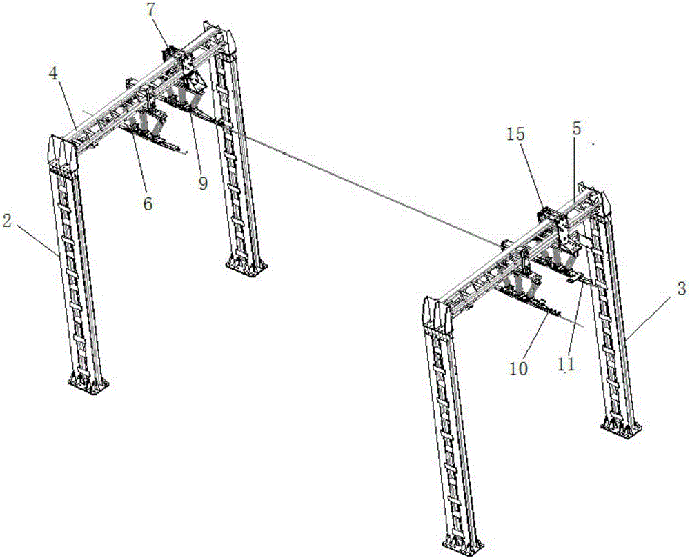
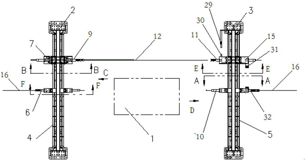
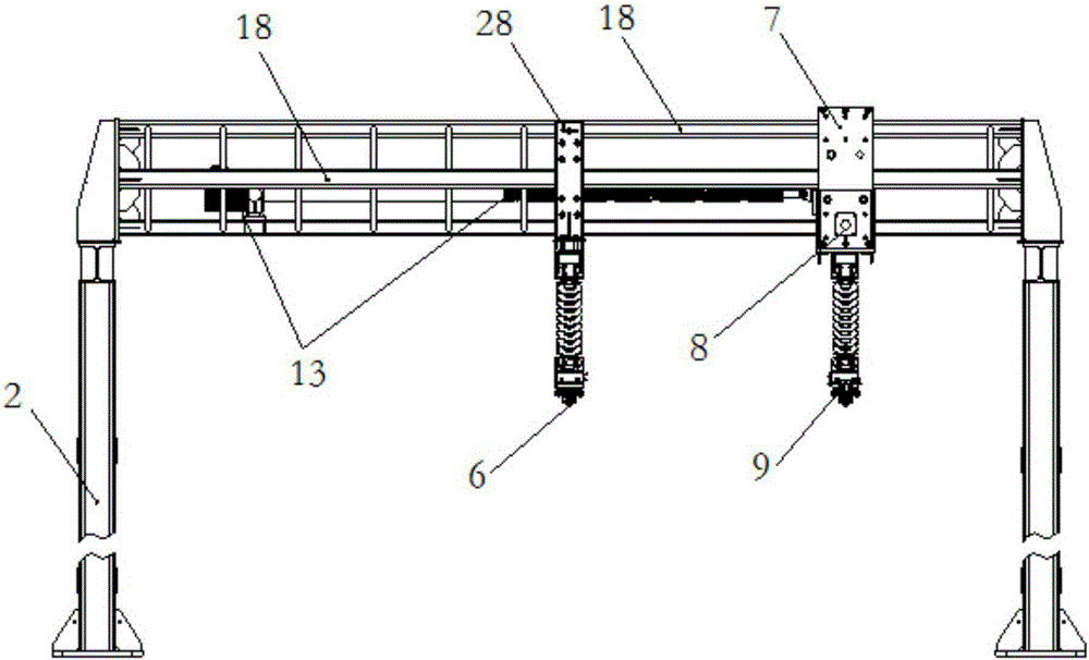
[0022] combined with Figure 1-7 Specific embodiments of the present invention will be described in detail.

[0023] A mobile catenary for an electrified railway coal charging station, comprising a left gantry 2 and a right gantry 3 located on both sides of a hopper bin 1, and the left gantry 2 and right gantry 3 straddle the two sides of the funnel bin 1 On the line on the side, the left crossbeam 4 on the top of the left gantry 2 and the middle part of the right crossbeam 5 on the top of the right gantry 3 are rigidly suspended by insulators 17 to have symmetrical left fixed busbars 6 and right fixed busbars. 10. The left crossbeam 4 is equipped with a left moving trolley 7 that can move back and forth, and the left moving trolley 7 is located between the left fixed bus bar 6 and the rear column of the left gantry 2; the left moving trolley 7 is equipped with a The tension compensation trolley 8 that moves in the line direction, the left movement bus bar 9 is rigidly suspen...


PUM


Abstract

The invention discloses a mobile catenary for an electrified railway coaling station. A left portal frame and a right portal frame stretch across lines on the two sides of a hopper bin; a left fixed busbar and a right fixed busbar are rigidly suspended below the middles of a left cross beam and a right cross beam; a left moving trolley is mounted on the left cross beam; a tension compensation trolley is mounted on the left moving trolley; a left mobile busbar is rigidly suspended below the tension compensation trolley; a right moving trolley is mounted on the right cross beam; a right mobile busbar is rigidly suspended below the right moving trolley; a mobile contact line is connected between the left mobile busbar and the right mobile busbar; a left electric push rod and a right electric push rod mounted at the front parts of the left cross beam and the right cross beam are respectively connected with the left moving trolley and the right moving trolley so as to drive the mobile contact line to move forwards and backwards in the direction parallel to the lines; the tension compensation trolley moves to provide tension for the mobile contact line or release the tension of the mobile contact line; and the left fixed busbar and the right fixed busbar are respectively connected with flexible contact lines on the outer sides of the left fixed busbar and the right fixed busbar. During coaling, the mobile contact line is moved away, and the mobile contact line is moved to a position above the railway so as to provide electricity for an electric locomotive when a train enters and leaves a coaling zone.

Description

technical field [0001] The invention belongs to the technical field of rail transit rigid catenary, and in particular relates to a mobile catenary for an electrified railway coal charging station. Background technique [0002] The electrified coal transportation special railway needs to be equipped with a coal loading station, and the quantitative hopper bin and coal chute of the coal loading station are erected above the line, and the space above 6.5m on the rail surface is occupied, and the section about 9m long along the line direction cannot be erected. The flexible catenary can not use the inertia of the train to break through the non-electric area. It has become a common problem for the electric locomotive to pass through the funnel warehouse when it is charged. It is completed with double bows, which restricts the efficiency of the entire logistics chain. Contents of the invention [0003] Aiming at the above problems, the present invention designs a mobile catenar...

Claims


Application Information

Patent Timeline
Patent Type & Authority Applications(China)
IPC IPC(8): B60M1/00B60M1/26B60M1/20
Inventor 张旭峰徐天文郭如飞李望朱珺娥刘拴喜何保国王杰冯勇李东伟豆雯
Owner CHINA RAILWAY HIGH SPEED ELECTRIFICATION EQUIP CORP LTD
Why Eureka
Try Eureka