
A Visualized Software-Hardware Collaborative Development Method

A software-hardware collaboration and software technology, applied in the field of visual software-hardware collaborative development, can solve problems such as low product reliability and stability, and achieve the effects of improving development efficiency, ensuring product quality, and improving cost performance.

Active Publication Date: 2019-01-01
XUJI GRP +3
View PDF3 Cites 2 Cited by
  • Summary
  • Abstract
  • Description
  • Claims
  • Application Information

AI Technical Summary

Problems solved by technology

[0004] The purpose of the present invention is to provide a visual software and hardware collaborative development method to solve the problem of low reliability and stability of the developed product caused by the manual code writing method in the current embedded system development

Method used


Image

  • A Visualized Software-Hardware Collaborative Development Method
  • A Visualized Software-Hardware Collaborative Development Method
  • A Visualized Software-Hardware Collaborative Development Method

Examples


Embodiment Construction

[0024] The specific embodiments of the present invention will be further described below in conjunction with the accompanying drawings.

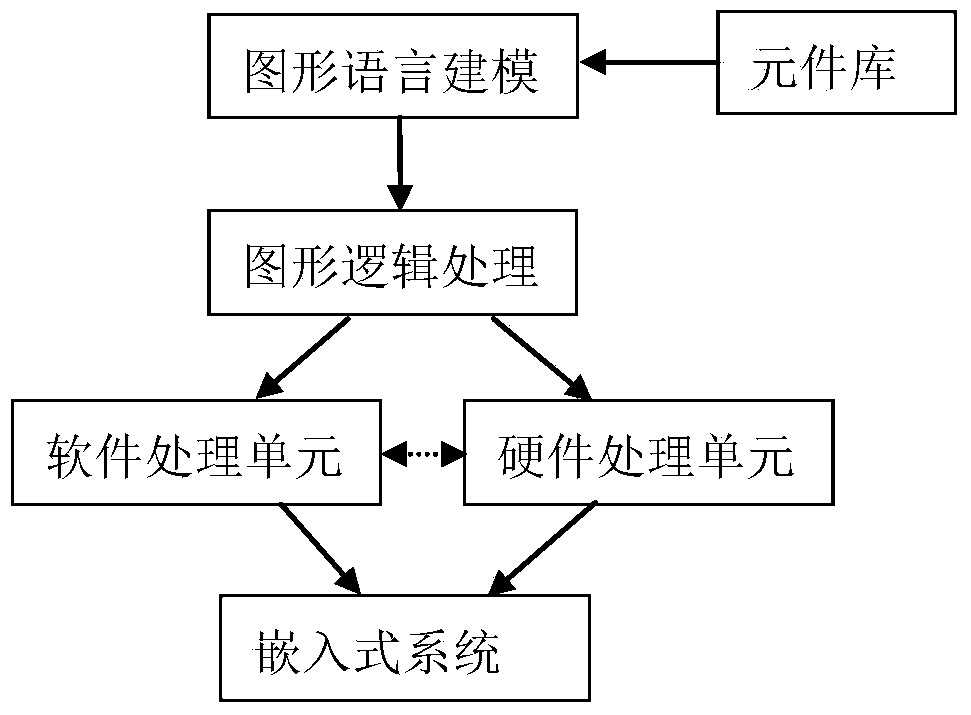
[0025] In view of the above situation, the present invention provides a visual software and hardware collaborative development method, which uses a unified graphic language to describe software and hardware functions, and establishes an application business model; users perform logical configuration through components and connections, and describe software and hardware functions. There is no need to write any code, and there is no need to care about the communication details of software and hardware, which reduces the requirements of developers, improves development efficiency and ensures system reliability and stability.

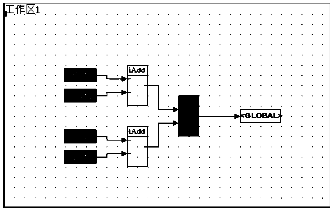
[0026] The overall working principle diagram of the present invention is as figure 1 As shown, according to the attributes of the components themselves, a component library is established. The components in the component ...


PUM


Abstract

The invention relates to a visual software and hardware collaborative development method, and belongs to the technical field of embedded system development. The method comprises the steps that corresponding software and hardware models are set up by means of components in a component library according to the software and hardware functions described by a user, a software object file and other collaborative FPGA object files are generated according to codes corresponding to all the components in the models, software and hardware collaborative development can be conducted in one development environment, collaboration and communication details of software and hardware do not need to be concerned, the developing efficiency is improved, and meanwhile a software and hardware interface is provided for the user, software and hardware resources can be fully utilized, and the cost performance of a system is improved; by means of a graphical development mode, the user does not need to write codes, the development errors are reduced, and the product quality is guaranteed.

Description

technical field [0001] The invention relates to a visual software and hardware collaborative development method, which belongs to the technical field of embedded system development. Background technique [0002] At present, high-performance embedded systems generally include CPU and FPGA to handle high-complexity and high-real-time tasks. CPU handles high-complexity tasks, while FPGA handles high-real-time tasks. However, because the existing hardware platform and software platform are independent parts, they are developed by two teams separately without much coordination. Generally, the development of CPU software belongs to the category of software platform. The development of FPGA is closely related to hardware and belongs to the category of hardware development. The resource software platform provided by the design of hardware platform cannot fully play its role, and the performance and efficiency of software running on the hardware platform are also insufficient. reach...

Claims


Application Information

Patent Timeline
Patent Type & Authority Patents(China)
IPC IPC(8): G06F8/20
Inventor 陈献庆包伟杨智德宋彦锋李旺徐艳艳马卫平李杰叶留义赵丽娜杨健周东杰郑拓夫
Owner XUJI GRP
Learn More