
Transfer method of optical module firmware visualization

A conversion method and optical module technology, which is applied in the field of optical fiber communication, can solve problems such as low efficiency of firmware development, achieve visual development, save communication time, and realize the effect of visual testing

Active Publication Date: 2013-03-20
SOURCE PHOTONICS CHENGDU
View PDF3 Cites 0 Cited by
  • Summary
  • Abstract
  • Description
  • Claims
  • Application Information

AI Technical Summary

Problems solved by technology

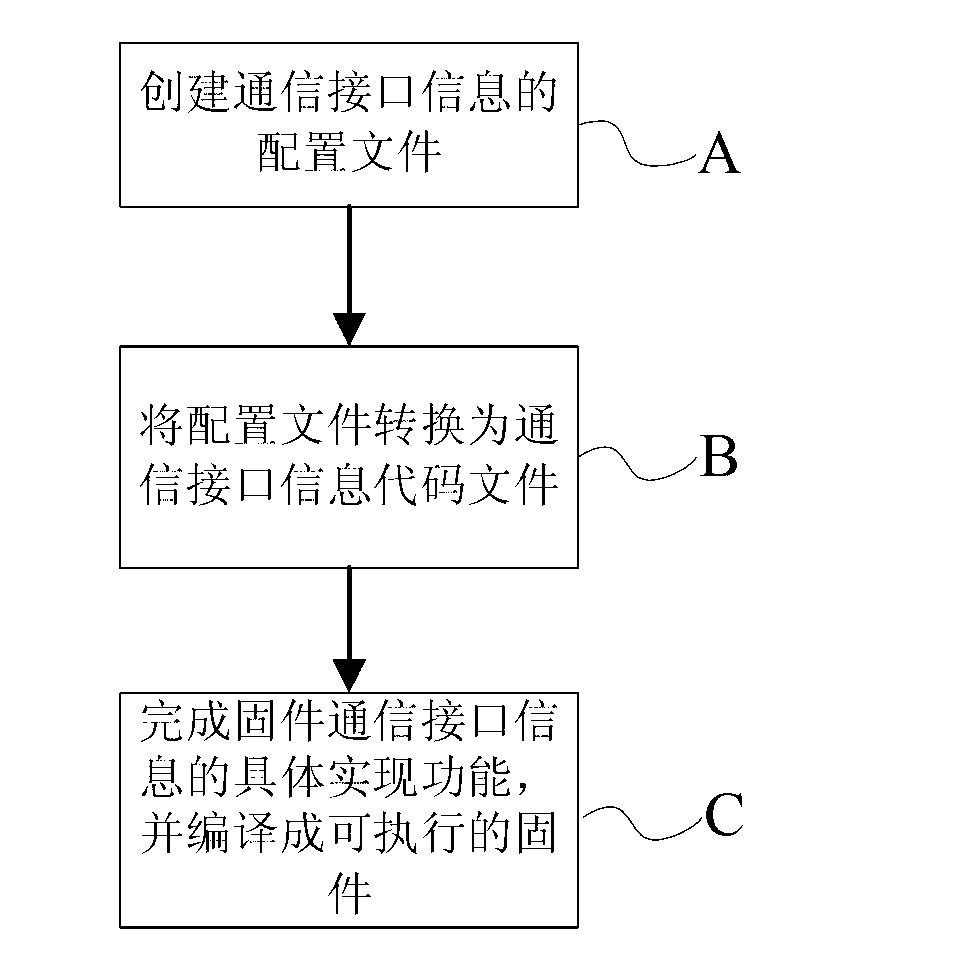
[0003] The purpose of the present invention is to overcome the inefficiency of firmware research and development caused by the communication of optical module firmware research and development in the existing methods, and provide a visual conversion method for optical module firmware, through which the visual research and development of optical module firmware can be realized

Method used


Image

  • Transfer method of optical module firmware visualization
  • Transfer method of optical module firmware visualization
  • Transfer method of optical module firmware visualization

Examples


Embodiment Construction

[0022] The present invention will be further described in detail below in conjunction with test examples and specific embodiments. However, it should not be understood that the scope of the above subject matter of the present invention is limited to the following embodiments, and all technologies realized based on the content of the present invention belong to the scope of the present invention.

[0023] The optical module and the system can realize information transmission through various communication interfaces, such as I 2 C interface, SPI interface, UART interface, MDIO interface etc., in the present embodiment with I 2 The C interface is used as an example to describe the method of the present invention in detail.

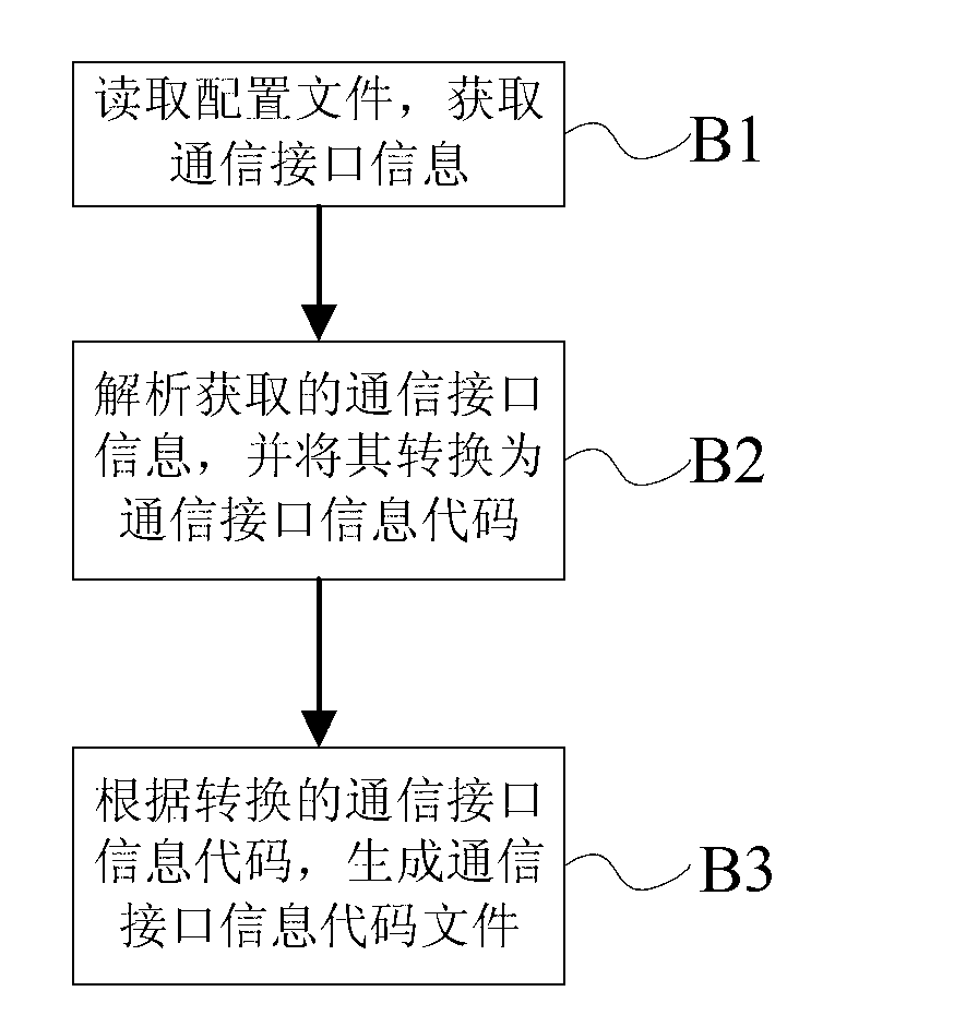
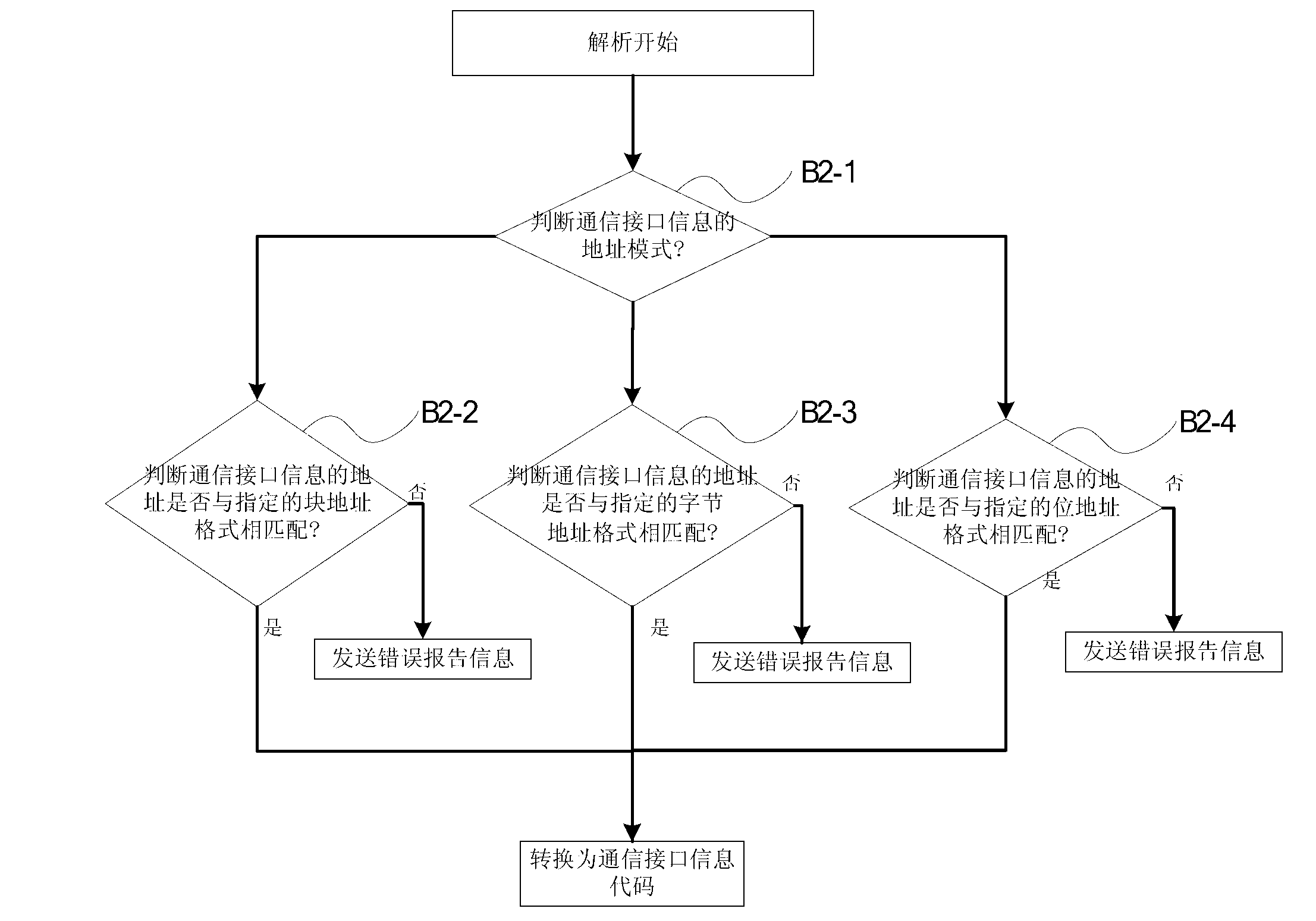
[0024] The visual conversion method of optical module firmware of the present invention is: before writing firmware program, first create all I that comprise optical module 2 C communication interface information (i.e. I 2 C information) configuration file...


PUM


Abstract

The invention discloses a transfer method of optical module firmware visualization, and belongs to the field of optical fiber communications. The transfer method includes the following steps: a configuration file including all communication interface information of the optical module is created; the configuration file is transferred to a communication interface information code file; concrete realization function of the communication interface information of the firmware is accomplished, and the communication interface information is compiled to an executable firmware. According to the transfer method of the optical module firmware visualization, the configuration file including all the communication interface information of the optical module is created before research and development of the firmware, and the configuration file is transferred to the communication interface information code file, and therefore a firmware researching and developing engineer and a firmware testing engineer can directly check a communication interface information code in the communication interface information code file; visual research, development and test of the optical module firmware is achieved; researching, developing and testing efficiency of the firmware is improved; and researching and developing period of the firmware is shortened greatly.

Description

technical field [0001] The invention relates to the field of optical fiber communication, in particular to a visual conversion method for optical module firmware. Background technique [0002] An optical module is a device that realizes photoelectric conversion, and is composed of an optoelectronic device, a functional circuit and an optical interface. Optical module firmware (Firmware) is an executable program solidified in the PROM, EEPROM or FLASH ROM inside the optical module, which is responsible for coordinating and controlling various devices inside the entire optical module to make it work normally according to the predetermined function. In the existing optical module firmware development process, the optical module firmware is usually jointly developed by multiple firmware engineers, and each person is only responsible for a part of it. Because firmware engineers often need to cross-obtain relevant firmware information that the other party is responsible for, and ...

Claims


Application Information

Patent Timeline
Patent Type & Authority Applications(China)
IPC IPC(8): G06F11/36
Inventor 曾海峰熊亚希黄伟余军鲁妹玲
Owner SOURCE PHOTONICS CHENGDU
Learn More