Method for predicting milling surface errors based on dynamic workpiece clamping system

A technology of milling processing and prediction method, which is applied in special data processing applications, instruments, electrical digital data processing, etc., and can solve problems such as difficult processing of weak rigidity parts

Active Publication Date: 2015-12-23
BEIJING INSTITUTE OF TECHNOLOGYGY
View PDF3 Cites 15 Cited by
  • Summary
  • Abstract
  • Description
  • Claims
  • Application Information

AI Technical Summary

Problems solved by technology

[0005] In view of this, the object of the present invention is to provide a milling surface error prediction method based on a dynamic workpiece-clamping system, which solves the technical problem of difficult machining of parts with weak stiffness

Method used


Image

  • Method for predicting milling surface errors based on dynamic workpiece clamping system
  • Method for predicting milling surface errors based on dynamic workpiece clamping system
  • Method for predicting milling surface errors based on dynamic workpiece clamping system

Examples


Embodiment Construction

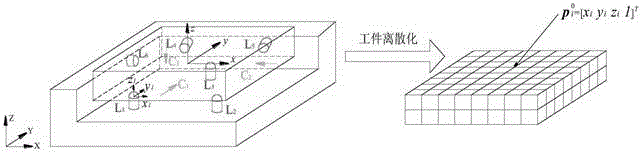
[0042] The following is a specific simulation example based on the established workpiece dynamic milling error prediction method.

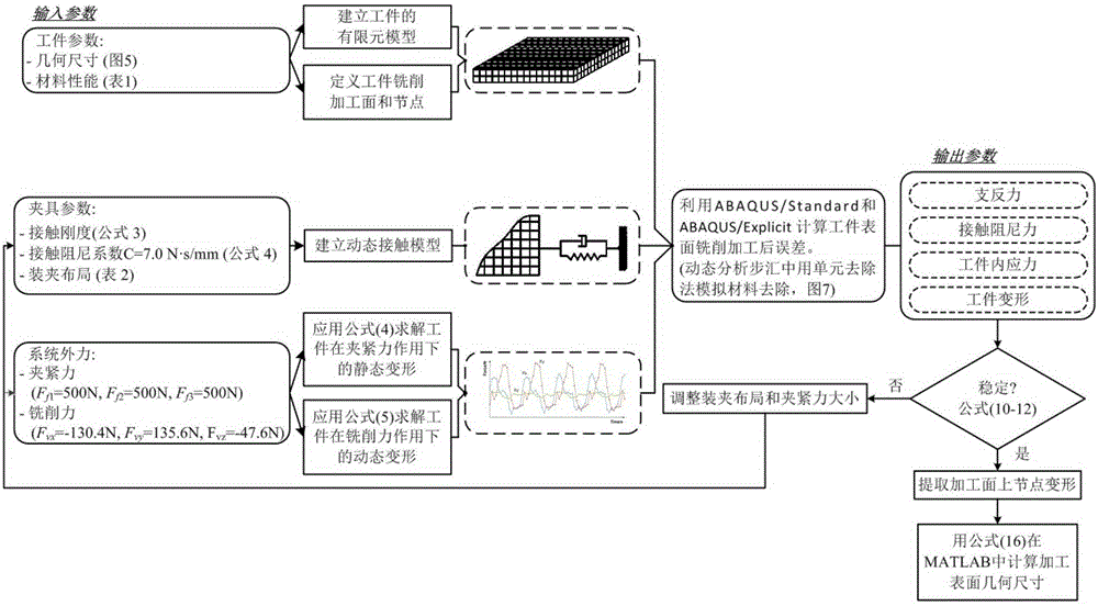
[0043] Firstly, the workpiece is a hexahedral flat plate with a size (length×width×height) of 100mm×100mm×14mm. Through milling, an open slot with a size of 100mm×10mm×1mm is processed on the workpiece. The 3-2-1 positioning criterion is adopted when the workpiece is processed. The material properties of the workpiece and the positioning / clamping components are shown in Table 1, and the layout of the positioning / clamping components is shown in Table 2. The clamping forces at C1, C2, and C3 are all 500N .

[0044] Table 1 Material Properties of Workpiece and Positioning / Clamping Components

[0045]

[0046] Table 2 Positioning / Clamping Component Coordinates

[0047]

[0048] ABAQUS6.11 software is used for finite element calculation, and the finite element analysis example model is established. The finite element model adopts the 8-node hex...


PUM


Abstract

The invention provides a method for predicting milling surface errors based on a dynamic workpiece clamping system. The technical problem that a weak-rigidity part is difficult to machine is solved. The method includes the following steps of firstly, establishing a coordinate system of a workpiece and positioning element system; secondly, establishing a workpiece and positioning element contact model according to the coordinate system of the workpiece and positioning element system, wherein when a positioning element is a round head element, the contact rigidity between the positioning element and a workpiece nonlinearly changes while the normal contact force changes; thirdly, establishing a workpiece and positioning element system model through the combination of the workpiece and positioning element contact model; fourthly, judging the stability of the workpiece and positioning element system according to the workpiece and positioning element system model; fifthly, predicting and calculating machining errors on the premise that the workpiece and positioning element system is stable.

Description

technical field [0001] The invention belongs to the technical field of mechanical manufacturing, and in particular relates to a milling surface error prediction method based on a dynamic workpiece-clamping system. Background technique [0002] Metal cutting deformation is a common problem in the manufacturing industry, and it is a bottleneck problem that affects processing accuracy. Especially for parts with weak stiffness, workpiece deformation becomes the main factor leading to machining errors, which seriously affects the machining accuracy and surface quality of workpieces. Therefore, it is of great significance to predict the processing deformation of parts, and to reduce the processing deformation of parts and improve product quality by improving the processing technology. Factors that cause workpiece deformation include material properties and structural properties of the workpiece, initial residual stress of the blank, cutting force and cutting heat, clamping force,...

Claims


Application Information

Patent Timeline
Patent Type & Authority Applications(China)
IPC IPC(8): G06F17/50
Inventor 王西彬董朝辉焦黎解丽静袁美霞王昭
Owner BEIJING INSTITUTE OF TECHNOLOGYGY
Why Eureka
Try Eureka