Supercharge Your Innovation With Domain-Expert AI Agents!

Scanner Automatic Dirty/clean Window Detection

A scanner and window technology, which is used in the field of automatic detection of dirty/clean windows of scanners, and can solve problems such as image blurring

Active Publication Date: 2015-12-23
NCR CORP
View PDF8 Cites 2 Cited by
  • Summary
  • Abstract
  • Description
  • Claims
  • Application Information

AI Technical Summary

Problems solved by technology

All in all, this dust can then blur the image where the dust intervenes between the object and the sensor
An additional complicating factor is that dust enters the image sensor in different ways depending on whether the dust is caused by backlight provided by ambient lighting or by frontlight provided by the scanner's own lighting

Method used


Image

  • Scanner Automatic Dirty/clean Window Detection
  • Scanner Automatic Dirty/clean Window Detection
  • Scanner Automatic Dirty/clean Window Detection

Examples


Embodiment Construction

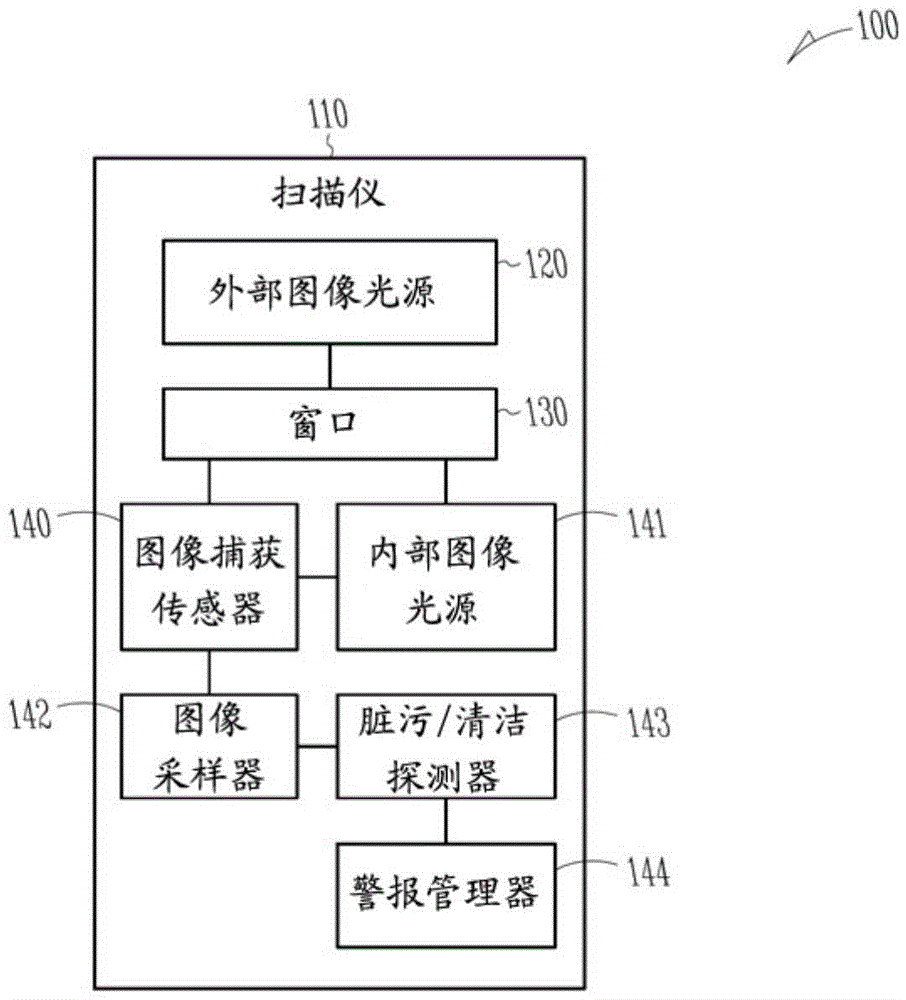
[0032] First refer to figure 1 , according to an example embodiment, depicts a schematic diagram 100 of components of an optical scanner 110 that automatically detects whether a window 130 of the optical scanner 110 is clean or not. It is noted, however, that the optical scanner 110 is shown schematically in a greatly simplified form, and only components relevant to understanding the illustrated embodiment are described. The same is true for the other illustrated components of the optical scanner 110 .

[0033] Also, for illustration purposes only, depicting ( figure 1 ) each component, and the layout of the presentation components. It is to be noted, however, that more or fewer components may be arranged in other ways without departing from the guidelines for automatic detection of dirty / clean windows presented herein and below.

[0034] In addition, the dirty / clean window automatic detection method and system presented herein and below may include all or some of the compo...


PUM


Abstract

An image from a window of a scanner is taken and analyzed to determine whether the image is relevant to dirt or debris on the window. When the image is relevant to dirt or debris, the size and amount of the dirt or debris is compared to a threshold and when the threshold is exceeded an alert is raised to have the window cleaned of the dirt or debris.

Description

technical field [0001] The present invention relates to automatic detection of dirty / clean windows of scanners. Background technique [0002] Imaging barcode scanners operate in environments that are constantly exposed to dust, debris, and other contaminants. The above-mentioned dust and the like will adhere to one or more optical windows of the scanner, which will inevitably reduce the quality of images captured by the scanner. In turn, reduced image quality naturally detracts from the performance of the scanning device. [0003] In an imaging barcode scanner, light travels from an imaging object through one or more optical components to one or more image sensors. Optical components perform best when they are free of dust, grease, and any other contaminants that can scatter, absorb, or break down the light reflected from an object to the sensor. Barcode scanners operating in point-of-sale (POS) systems are typically continuously exposed to environmental dust, etc., some ...

Claims


Application Information

Patent Timeline
IPC IPC(8): G06K7/10G06T7/00
CPCG06K7/0095G01N21/94G01N21/8803G01N21/8851G01N21/958G01N2201/061G01N2201/12
Inventor 西奥多·黑斯克 三世
Owner NCR CORP
Features
  • R&D
  • Intellectual Property
  • Life Sciences
  • Materials
  • Tech Scout
  • Unparalleled Data Quality
  • Higher Quality Content
  • 60% Fewer Hallucinations
Learn More