
Ultrasonic transducer and ultrasonic flow meter

An ultrasonic transducer and ultrasonic signal technology, applied in the directions of sound-producing equipment, flow/mass flow measurement, liquid/fluid solid measurement, etc., can solve problems such as measurement errors and achieve the effect of reducing damage

Active Publication Date: 2015-12-23
ENDRESS HAUSER FLOWTEC AG
View PDF4 Cites 2 Cited by
  • Summary
  • Abstract
  • Description
  • Claims
  • Application Information

AI Technical Summary

Problems solved by technology

However, if the piezoelectric element is not placed flat on the metal disk, but is supported on the curved edge of an angled sheet metal element, measurement errors and / or distributed ultrasonic signals can occur

Method used


Image

  • Ultrasonic transducer and ultrasonic flow meter
  • Ultrasonic transducer and ultrasonic flow meter
  • Ultrasonic transducer and ultrasonic flow meter

Examples


Embodiment Construction

[0037] Figure 6 There is shown an ultrasound transducer 1 generally known and described in EP0974814B1, the disclosure of which is fully incorporated herein by reference.

[0038] The ultrasonic transducer 1 has an arrangement of a piezoelectric element 2 and a metal disk 4 . The ultrasound transducer also has a coupling element 3 . This coupling element 3 is also often referred to as a coupling body. Coupling elements are often designed as wedges and are therefore called coupling wedges by experts.

[0039] In the exemplary embodiment the coupling element is also designed as a coupling wedge. In the following, the form and function of the coupling element will be explained in detail.

[0040] The basic shape of the coupling element is cylindrical with a shell surface and two bottom surfaces. One of the two bottom surfaces is angled.

[0041] Compared to known coupling elements, the inventive coupling element has an oblique bore-shaped special recess 5 in which the piez...


PUM


Abstract

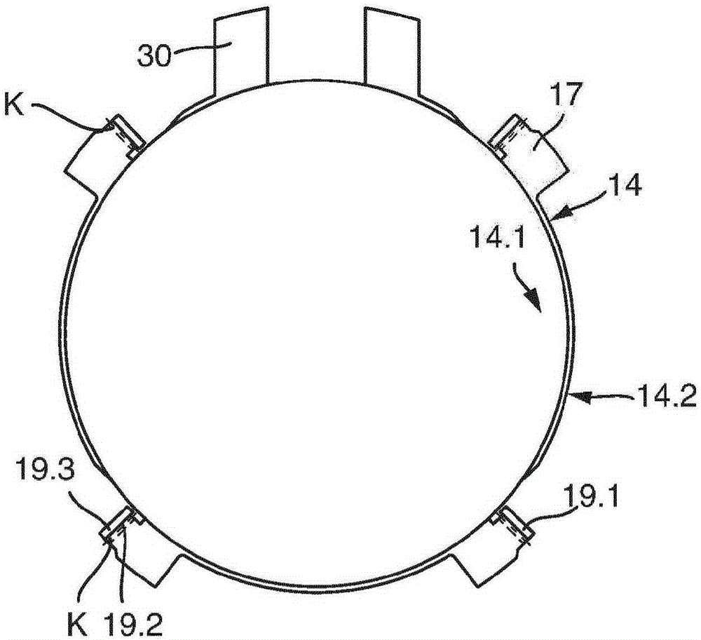
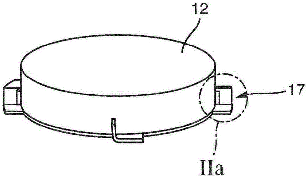
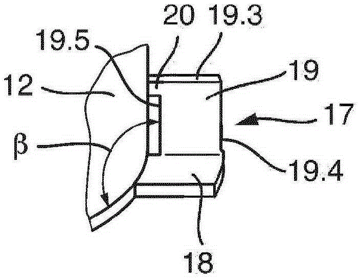
The invention concerns an ultrasonic transducer, comprising a coupling element which has a first recess, the first recess being provided for the arrangement of a piezoelectric element which feeds an ultrasound signal into the coupling element, and there being disposed between the piezoelectric element and the coupling element an intermediate layer which comprises a metal disc, the metal disc comprising retaining elements (a) each with a first segment lying on the same plane as the metal disc and projecting radially from the perimeter of the metal disc and (b) each having a second segment which adjoins the first segment, projects from the plane of the metal plate and is connected to the first segment.

Description

technical field [0001] The invention relates to an ultrasonic transducer according to the preamble of claim 1 and an ultrasonic flow meter according to claim 8 . Background technique [0002] In the field of mounting of ultrasound transducers, many different arrangements and layer sequences are known. [0003] General EP0974814B1 describes a coupling element with a support or contact area, the coupling element having a recess for receiving a piezoelectric element. A metal disk is arranged between the coupling element and the piezoelectric element. The metal element is glued on a plane relative to the slope of the support, where the plane is at the same time the bottom surface of the recess. To center and stabilize the piezoelectric element against lateral movement, the metal disc has angled foil elements protruding from its horizontal plane. Such a construction has proven its fundamental value, especially because of its high-temperature alternating stress. However, if th...

Claims


Application Information

Patent Timeline
Patent Type & Authority Applications(China)
IPC IPC(8): G01F1/66B06B1/06G10K11/02
CPCG01F1/662G10K11/004
Inventor 阿希姆·维斯特安德里亚斯·贝格尔
Owner ENDRESS HAUSER FLOWTEC AG
Learn More