Stabilizing device for fixing wire coil support

A technology of stabilizing device and disk bracket, which is applied in the directions of transportation and packaging, delivery of filamentous materials, and thin material processing, etc. It can solve the problems of weakened support strength, large overall weight of the support, and low operating efficiency, etc., to achieve increased strength , Improve installation efficiency and improve work efficiency

Active Publication Date: 2021-08-24
江苏亚盛金属制品有限公司
View PDF13 Cites 1 Cited by
  • Summary
  • Abstract
  • Description
  • Claims
  • Application Information

AI Technical Summary

Problems solved by technology

[0003] The existing patent No. CN107176501B proposes a brake bracket type reel, which includes a main frame and a reel. Arranged horizontal sub-boards, two vertically arranged vertical sub-columns and an intermediate support plate connecting the two horizontal sub-plates. The middle support plate is between the two horizontal sub-plates. The support frame is equipped with a support channel with the opening facing upwards and used to accommodate the main shaft. The main shaft passes through the support channel. The main frame is equipped with a hydraulic brake for stopping the main shaft, which can effectively take up the wire. , Pay-off, simple disassembly and assembly, low transportation difficulty, high assembly efficiency, and convenient use; it can automatically limit the speed when the speed is too fast, and has a multi-level speed limit function, which is safe and stable, but because Due to the mobile function requirements of some equipment, the need for different lengths of wire reels, and the need for convenience in layout planning, it is necessary to frequently adjust the position of the equipment, so the bracket also needs to follow the equipment to adjust the position. If the bracket is set in an unfixed state , the stress strength of the bracket will be weakened. When the stainless steel rope is strangled and killed, the automation equipment will directly pull the wire reel and the bracket together, which will pose a certain safety hazard to the equipment and staff. When the bracket is set In a fixed state, when fixing the bracket, it is necessary to open holes on the bottom surface and install expansion bolts and other operations, and when adjusting the position, it is necessary to destroy the expansion bolts. While the operation efficiency is low, it will cause irreversible damage to the ground and the bracket if it goes on for a long time. destroy
[0004] Existing patent No. CN210214354U proposes a heavy-duty cable reel pay-off bracket, including: a base, a load-bearing base, a rotating shaft, a bearing, a support plate, a support column and a placement platform, the bearing base is fixed on the upper center of the base, and one end of the rotating shaft is connected to the load-bearing The other end is connected with the middle part of the bottom surface of the support plate through the bearing, the rotating shaft and the inner ring of the bearing are in interference fit, the bottom of the placing platform is fixedly connected with the support plate through three support columns, and the top of the placing platform is provided with three vertically arranged The limit bar is provided with several vertically distributed limit screw holes, and horizontally arranged limit studs are arranged in the limit screw holes; the three support columns and the three limit bars are respectively arranged in a triangular distribution and The centers of the two triangles are on the same vertical line as the axis of rotation. The bottom of the base is provided with feet for shock absorption and stabilization of the heavy-duty cable reel pay-off bracket. The feet include an upper end cover, a shock-absorbing column and a lower end cover. The column is fixed between the upper end cover and the lower end cover, and the top outer wall and the lower end outer wall of the shock-absorbing column are respectively close to the inner walls of the upper end cover and the lower end cover. The lower end surface of the upper end cover and the upper end surface of the lower end cover are offset, the top of the upper end cover is provided with a connecting screw for connecting with the base, the bottom of the lower end cover is fixed with a support plate, and the left and right ends of the support plate are provided with screw holes. To meet the needs of convenient position adjustment and high strength, and the overall weight of the bracket is relatively large, making it more difficult to adjust the position conveniently

Method used


Image

  • Stabilizing device for fixing wire coil support
  • Stabilizing device for fixing wire coil support
  • Stabilizing device for fixing wire coil support

Examples


Embodiment Construction

[0033] The following will clearly and completely describe the technical solutions in the embodiments of the present invention with reference to the accompanying drawings in the embodiments of the present invention. Obviously, the described embodiments are only some, not all, embodiments of the present invention. Based on the embodiments of the present invention, all other embodiments obtained by persons of ordinary skill in the art without making creative efforts belong to the protection scope of the present invention.

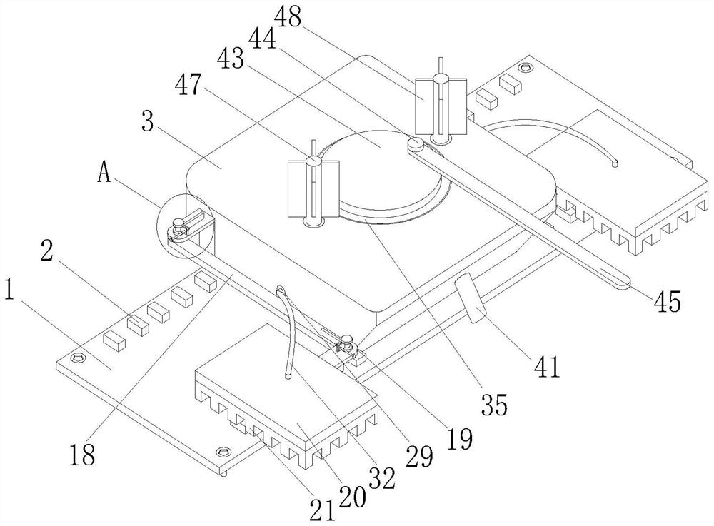
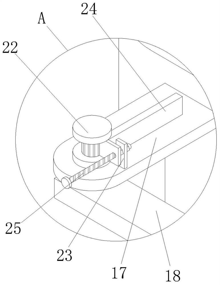
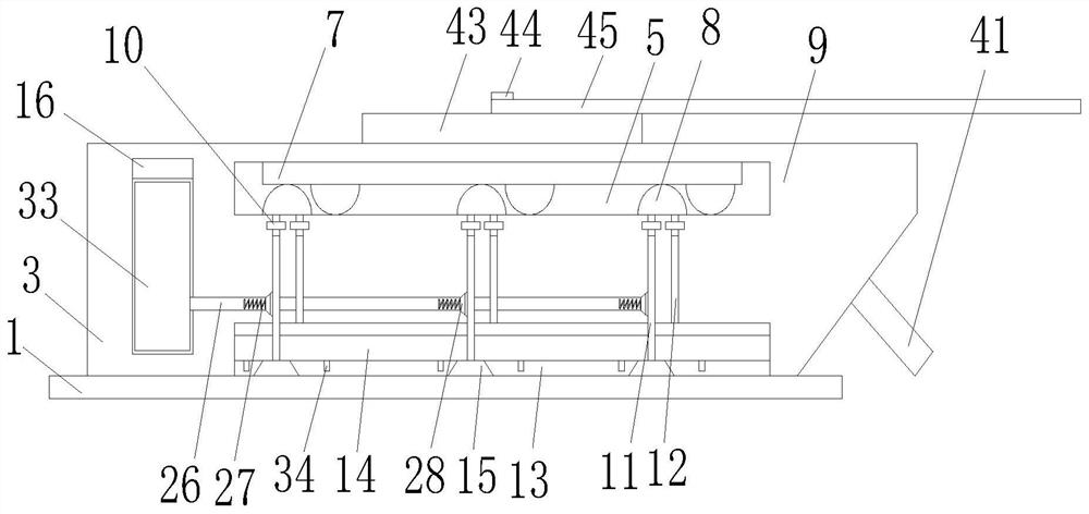
[0034] see Figure 1-8 , a stabilizing device for fixing the wire reel support, comprising a fixed base 1, holes are opened at the four corners of the top surface of the fixed base 1 and bolts are inserted therein, and several Insert block 2, a stable seat 3 is placed on the fixed base 1, several slots 4 are provided at equal intervals on both sides of the bottom, front and back of the stable seat 3, and the slots 4 are in a nested relationship with the insert...


PUM


Abstract

The invention relates to the technical field of stabilizing devices, and discloses a stabilizing device for fixing a wire coil support. The stabilizing device for fixing the wire coil support comprises a fixed base, a stabilizing seat is placed on the fixed base, a movable groove A is formed in the stabilizing seat, a plurality of elastic air cushions are fixedly connected to the bottom surface of the movable groove A at equal intervals, and sliding grooves are formed in the left side and the right side of the stabilizing seat. The inner wall of the sliding groove is sleeved with a fixing plate A, the inner wall of the fixing plate A is connected with a connecting plate through a rotating bearing, the end, away from the fixing plate A, of the connecting plate is sleeved with a fixing plate B, the end, away from the stabilizing base, of the fixing plate B is fixedly connected with a stabilizing plate, the bottom face of the fixing plate A is fixedly connected with a telescopic pad, and the bottom end of the telescopic pad is fixedly connected with the inner wall of the sliding groove. According to the arrangement of the stabilizing plate, the stabilizing plate is descended to apply pressure to supports, the supports are fixed to improve the stability of the supports, the problem that the supports are stressed and topple over is avoided on the premise that the supports are not fixed, the operation is simple, meanwhile, the two supports can be fixed at the same time, and the working efficiency is improved.

Description

technical field [0001] The invention relates to the technical field of stabilizing devices, in particular to a stabilizing device for fixing a coil support. Background technique [0002] In the automatic production of stainless steel rope, it is necessary to set up a wire reel to wind the stainless steel rope for the extraction of the stainless steel rope by the automation equipment, and in order to ensure the stability of the wire reel, a bracket will be set to support and fix the wire reel. [0003] The existing patent No. CN107176501B proposes a brake bracket type reel, which includes a main frame and a reel. Arranged horizontal sub-boards, two vertically arranged vertical sub-columns and an intermediate support plate connecting the two horizontal sub-plates. The middle support plate is between the two horizontal sub-plates. The support frame is equipped with a support channel with the opening facing upwards and used to accommodate the main shaft. The main shaft passes t...

Claims


Application Information

Patent Timeline
Patent Type & Authority Applications(China)
IPC IPC(8): B65H49/20
CPCB65H49/20
Inventor 蒋红兵韩俭刘振宇曹光明蒋红俊周江陶文明周雪峰
Owner 江苏亚盛金属制品有限公司
Why Eureka
Try Eureka