
A user equipment and a method for transmitting sounding reference signals

A technology for detecting reference signals and user equipment, which is applied in the field of signal transmission, can solve the problem of delaying the time to turn on SRS, and achieve the effect of saving signaling resources

Active Publication Date: 2015-12-23
TELEFON AB LM ERICSSON (PUBL)
View PDF6 Cites 2 Cited by
  • Summary
  • Abstract
  • Description
  • Claims
  • Application Information

AI Technical Summary

Problems solved by technology

It also delays the time to turn on the SRS, alternatively requiring a larger margin

Method used


Image

  • A user equipment and a method for transmitting sounding reference signals
  • A user equipment and a method for transmitting sounding reference signals
  • A user equipment and a method for transmitting sounding reference signals

Examples


Embodiment Construction

[0023] Briefly described, a UE operable for transmitting an SRS in a wireless communication network and a method performed by the UE are provided. The UE is adapted to determine when to transmit SRS and when not to transmit SRS based on eg different circumstances.

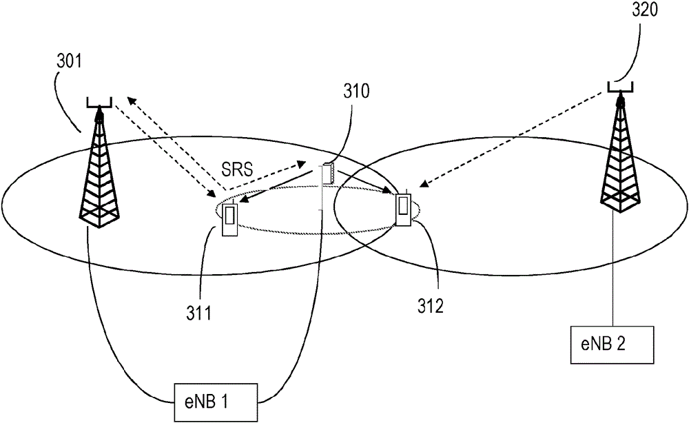
[0024] SRS can be used for many purposes and characteristics. In many cases, it is most useful around cell edges where there is maximum overlap of cells (i.e., coverage areas of network nodes). In this area, the selection of the best transmit and receive points to use can change rapidly. Also, in this region, the co-channel interference is strongest and the coordination gain is largest. Coordination gain refers to the gain from coordinating network nodes. In another area of ​​the cell, such as in the center of the cell, the use value of the SRS may be lower.

[0025] will now refer to Figure 1a and 1b , describing an exemplary embodiment of a method for transmitting an SRS performed by a UE. Figure 1a The me...


PUM


Abstract

A User Equipment, UE, operable to be used in a wireless communication network and a method performed by the UE for transmitting Sounding Reference Signals, SRSs are provided. The method comprises receiving (110) at least one transmission from at least one network node, and measuring (120) at least one radio quality indicator based on the received at least one transmission. The method further comprises comparing (130) the at least one measured radio quality indicator to at least a first threshold value; and transmitting, or refraining from transmitting, (140) SRSs based on a result of the comparison.

Description

technical field [0001] The present disclosure relates to the transmission of signals, and in particular, to the transmission of Sounding Reference Signals, SRS. Background technique [0002] Wireless communication networks and systems are growing both in the number of different services offered and the number of users using the different services. The increasing number of users and the increasing amount of traffic in wireless communication networks place increasing demands on the capacity and coverage on the network and / or system. One way to increase capacity and coverage is to place more network nodes or radio base stations RBS in the area covered by the wireless communication network. [0003] More recent technologies utilize higher and higher frequencies, which experience increased path loss with increasing frequency. Additionally, deployments in urban areas suffer from difficult propagation conditions. Due to these factors, RBSs tend to be deployed in increasingly tig...

Claims


Application Information

Patent Timeline
IPC IPC(8): H04W52/24
CPCH04L1/20H04L5/001H04L5/0048H04L5/006H04L5/0085H04L5/0035H04L25/0226H04W52/0245H04W52/0225Y02D30/70H04W72/21H04W72/23H04W72/542
Inventor A.西蒙斯森S.兰德斯特雷姆S.索伦蒂诺
Owner TELEFON AB LM ERICSSON (PUBL)
Learn More