
Electronic cigarette device

A technology of electronic cigarettes and driving devices, which is applied in the field of electronic products in the field of daily life, and can solve the problems of heating wire dry burning, coking, affecting cleaning and feeling, etc.

Active Publication Date: 2015-12-30
INNOKIN TECH
View PDF13 Cites 4 Cited by
  • Summary
  • Abstract
  • Description
  • Claims
  • Application Information

AI Technical Summary

Problems solved by technology

[0006] One is that the air intake hole of the atomizing core is set at the lower part of the atomization chamber, and the liquid guide fiber material is set at the upper part of the air intake hole. The liquid guide fiber material absorbs the e-cigarette liquid by osmosis, and when it reaches a saturated state, it will E-cigarette liquid seeps out, and the oozing e-cigarette liquid drips and gathers, and it will flow out from the air intake hole to a certain extent, and the general air intake hole cannot be closed, because after closing, the air cannot be sucked in, so you can’t smoke
In the state of not needing to smoke, the impact from the outside is that the e-cigarette liquid will flow out from the air intake hole, affecting the cleanliness and feeling
[0007] Second, due to the use of fibrous fluid-guiding substances, these fibrous substances are prone to coking when heated. When the coked fibrous substances lose their penetration, the overall atomizing core must be replaced.
When heating and atomizing at high temperature, if the liquid supply is not smooth, it is easy to cause the heating wire to burn dry, and it is easy to damage the heating wire and the fluid guide cotton.

Method used


Image

  • Electronic cigarette device
  • Electronic cigarette device
  • Electronic cigarette device

Examples


Embodiment

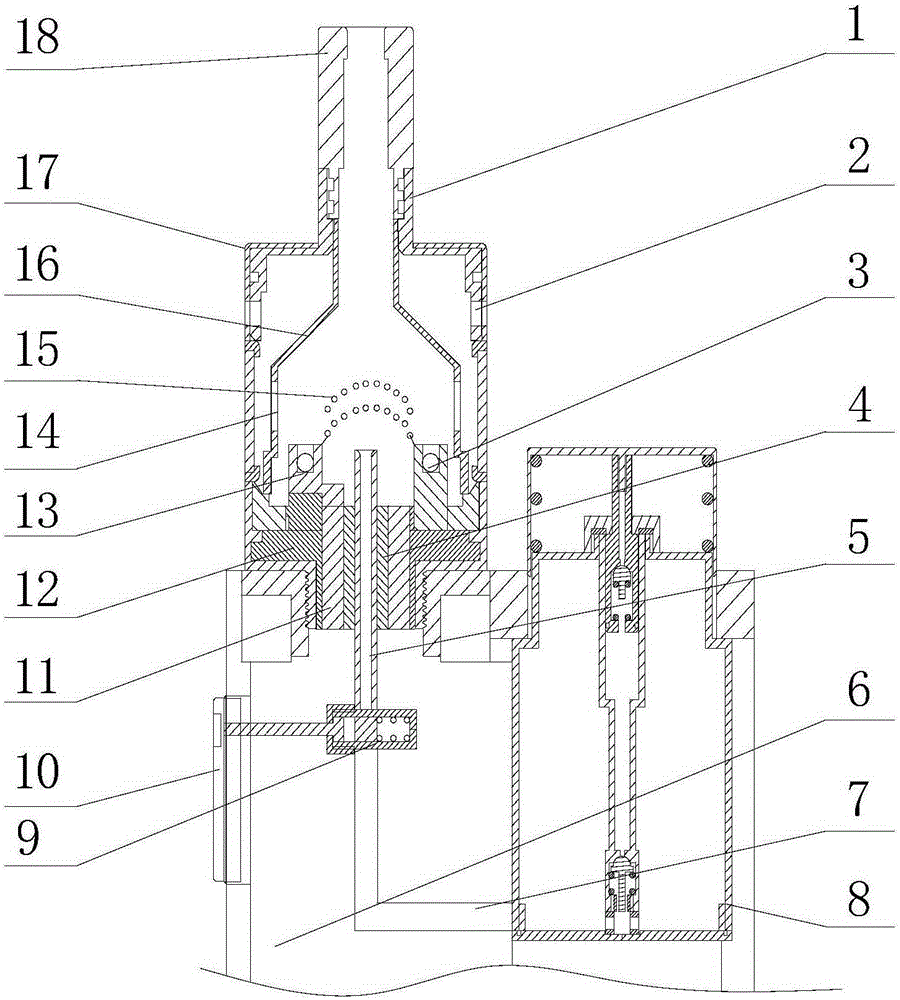
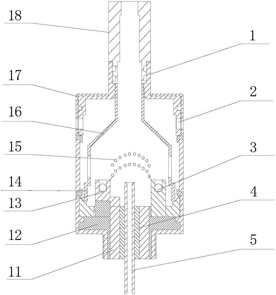
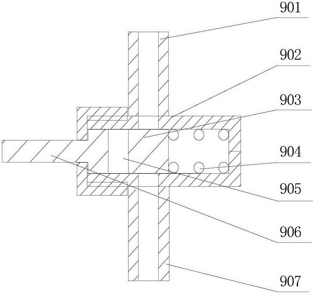
[0034] Such as figure 1Shown is a schematic diagram of a partial structure of the electronic cigarette device of the present invention. The electronic cigarette device is equipped with an electronic cigarette power supply and a control circuit 6, an electronic cigarette pressurized liquid supply device 7, a pressurized electronic cigarette smoke liquid nozzle 5, and an electronic smoke heating chamber. The shell 1 and the closed structure at the bottom end constitute it. The electronic cigarette power supply and control circuit 6 are arranged on the lower side, and the electronic cigarette pressurized liquid supply device 8 is arranged on the side of the electronic cigarette device. The pressurized e-cigarette liquid nozzle is fixedly arranged in the closed structure at the bottom of the atomization heating chamber, the outlet of the nozzle is arranged inside the atomization heating chamber, and the other end of the nozzle is connected to the electronic cigarette for pressuri...


PUM


Abstract

The invention discloses an electronic cigarette device. The electronic cigarette device comprises a cigarette liquid supplying device, a cigarette liquid atomizing device, a cigarette smoke suction device, a power source and a control circuit. The cigarette liquid supplying device is a pressurization liquid supplying device, the cigarette liquid atomizing device further comprises a pressurization cigarette liquid spraying tube and an atomizing heating chamber, the pressurization liquid supplying device and the pressurization cigarette liquid spraying tube are communicated through a pipeline, and a button switch is arranged on the pipeline. The atomizing heating chamber comprises a heating chamber shell and a heating wire arranged inside the shell. An outlet of the pressurization cigarette liquid spraying tube is arranged inside the atomizing heating chamber, is close to the heating wire and faces the heating wire. The cigarette smoke suction device comprises a suction cigarette holder communicated with the atomizing heating chamber. The button switch on the pressurization cigarette liquid communication pipeline synchronously controls the power source and a heating circuit of the control circuit.

Description

technical field [0001] The invention relates to an electronic product in the field of daily life, in particular to a novel electronic cigarette product. Background technique [0002] With the development of science and technology and society, people gradually realize the harm of smoking tobacco to the body, and gradually restrict or even ban tobacco smoking on certain occasions, so as not to affect people's health and the surrounding environment. However, since most smokers are already addicted to smoking, it is not easy to completely quit smoking, so there is an electronic cigarette product, which is currently popular in the market to atomize liquid containing nicotine by electric heating. Smoking this mist satisfies the needs of smokers, and has a tendency to replace tobacco to some extent. [0003] The current electronic cigarette products on the market use a heating wire to heat a liquid e-cigarette liquid, so that after the e-cigarette liquid is atomized, the smoke of ...

Claims


Application Information

Patent Timeline
IPC IPC(8): A24F47/00A24F40/10A24F40/48
CPCA24F40/10A24F40/48
Inventor 李建伟
Owner INNOKIN TECH
Learn More