
Punching die with opposite-punching mechanism

A punching die and elastic mechanism technology, which is used in punching tools, manufacturing tools, metal processing equipment, etc., can solve the problems of unreasonable punching die structure design, inability to meet modern production, and unusable round pipe workpieces. The effect of improving workpiece accuracy, improving service life and improving work efficiency

Inactive Publication Date: 2015-12-30
CHONGQING CHIHENG MOLD
View PDF7 Cites 1 Cited by
  • Summary
  • Abstract
  • Description
  • Claims
  • Application Information

AI Technical Summary

Problems solved by technology

[0002] In the field of mechanical processing, it is often necessary to process holes on the side wall of the round tube. The traditional processing methods are mostly processed by drilling or milling. These processing methods are too inefficient to meet the needs of modern production.
[0003] In recent years, some punching dies have appeared, which can punch holes on the side wall of the round tube, but the structural design of these punching dies is not reasonable enough. When punching, they can only punch on one side of the round tube at a time. In the field of processing, it is often necessary to open holes on two opposite side walls of the round tube. When using the existing punching die for two-way opening, the method is: first open the hole on one side, then adjust the position of the round tube and then open the hole on the other side. side opening
Although this method can complete the punching work, it often has the problem of inaccurate hole positions, which makes the processed round tube workpieces unusable and seriously affects the normal production work.

Method used


Image

  • Punching die with opposite-punching mechanism
  • Punching die with opposite-punching mechanism
  • Punching die with opposite-punching mechanism

Examples


Embodiment 1

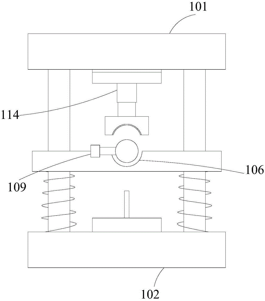
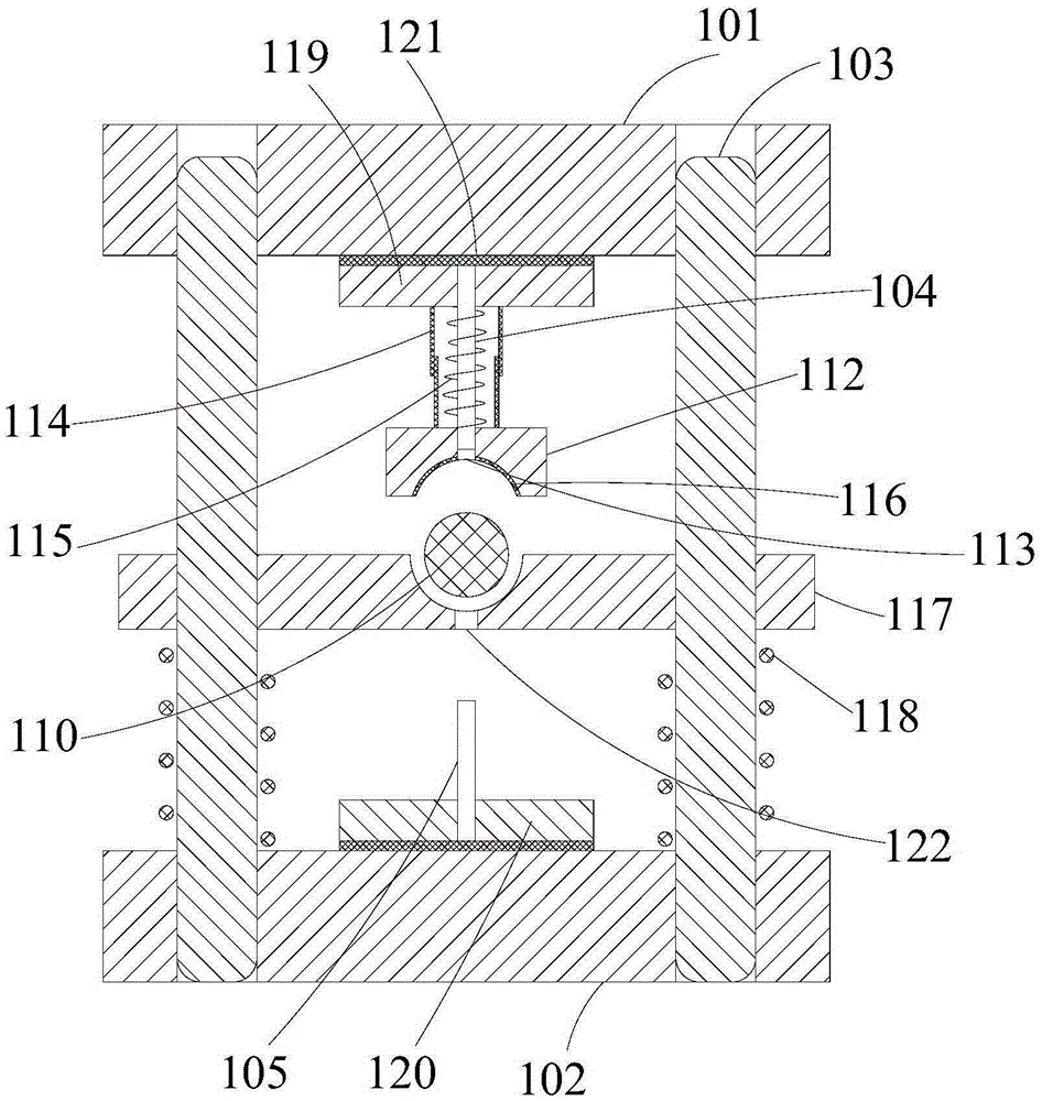
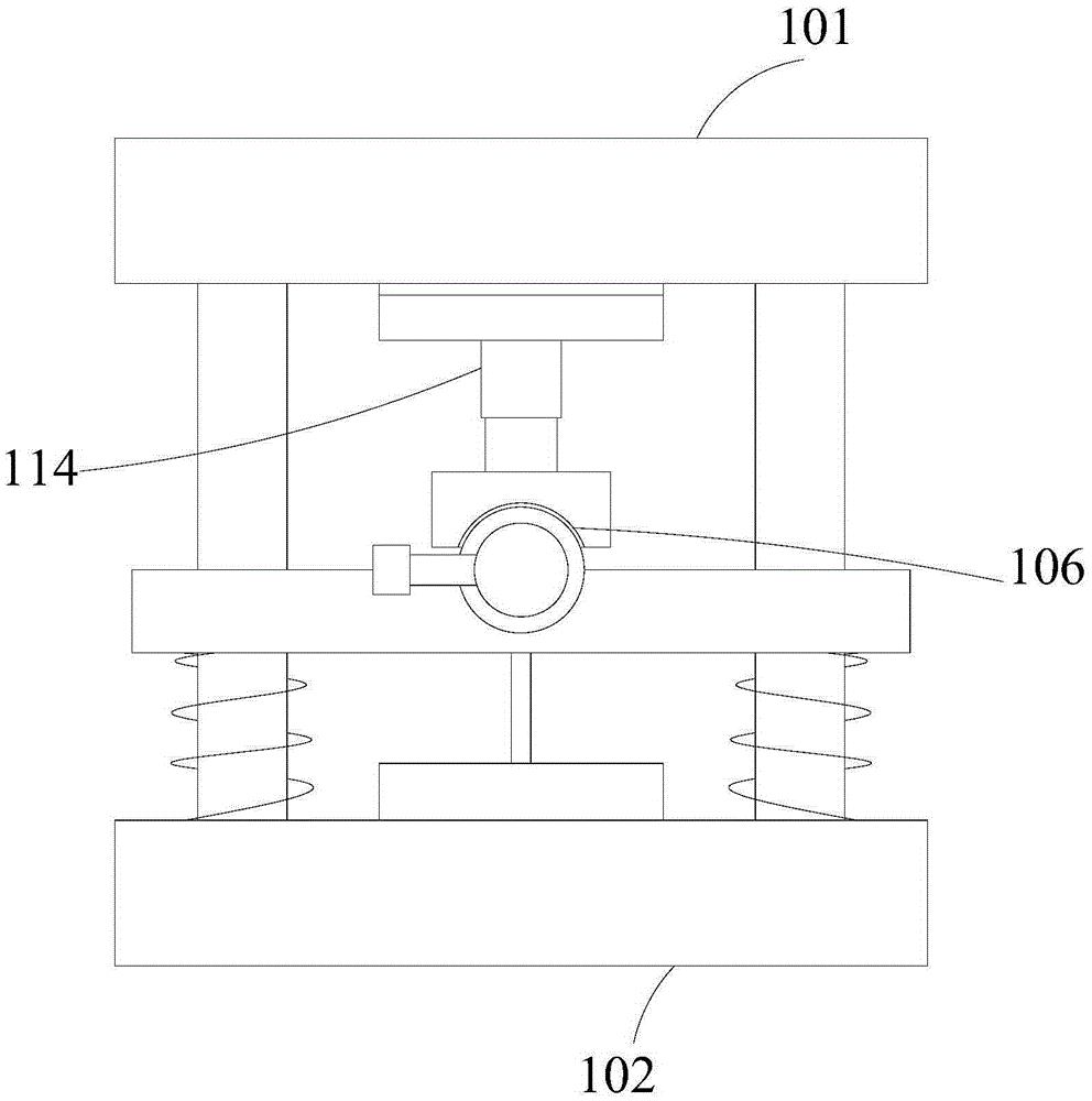
[0077] A punching die with a hedging mechanism, comprising an upper die base 101 and a lower die base 102, the upper die base 101 and the lower die base 102 are connected by a guide post 103, and an upper punch 104 is connected to the bottom of the upper die base 101; The top of the lower mold base 102 is also connected with the lower punch 105, between the upper mold base 101 and the lower mold base 102 is provided with an intermediate mold base 117, the intermediate mold base 117 is connected with the lower mold base 102 by a return spring 118, and the return spring 118 Sleeved on the outside of the guide post 103; the middle mold base 117 is provided with a round tube placement part 106, and the round tube placement part 106 is an arc-shaped sinker structure, and the bottom of the arc-shaped sinker is provided with the bottom of the middle mold base 117. The circular hole 122.

[0078] Upper punch 104 is connected with upper die base 101 through upper fixing seat 119, and l...


PUM


Abstract

The invention provides a punching die with an opposite-punching mechanism, and belongs to the field of dies. The punching die with the opposite-punching mechanism comprises an upper die seat and a lower die seat which are connected by a guide column, wherein the bottom of the upper die seat is connected with an upper convex die; the top of the lower die seat is also connected with a lower convex die; a middle die seat is arranged between the upper die seat and the lower die seat and is connected with the lower die seat by a rest spring; the rest spring is arranged on the outer part of the guide column in a sleeving manner; a round pipe placing part is arranged on the middle die seat and is in an arc-shaped sinking groove structure; and the bottom of the arc-shaped sinking grove is provided with a round hole communicated with the bottom of the middle die seat. The punching die can punch a round pipe from two directions of the round pipe so as to finish the punching on two side hole positions of the round pipe, so that the working efficiency is improved, the device input is reduced, the workpiece accuracy is improved, and enterprise benefits can be promoted directly.

Description

technical field [0001] The invention relates to the field of molds, in particular to a punching die with a hedging mechanism. Background technique [0002] In the field of mechanical processing, it is often necessary to process holes on the side wall of the round tube. The traditional processing methods are mostly processed by drilling or milling. These processing methods are too inefficient to meet the needs of modern production. [0003] In recent years, some punching dies have appeared, which can punch holes on the side wall of the round tube, but the structural design of these punching dies is not reasonable enough. When punching, they can only punch on one side of the round tube at a time. In the field of processing, it is often necessary to open holes on two opposite side walls of the round tube. When using the existing punching die for two-way opening, the method is: first open the hole on one side, then adjust the position of the round tube and then open the hole on ...

Claims


Application Information

Patent Timeline
Patent Type & Authority Applications(China)
IPC IPC(8): B21D28/34
Inventor 杨静
Owner CHONGQING CHIHENG MOLD
Learn More