
A kind of lead parts casting equipment

A technology of lead parts and equipment, which is applied in the field of lead parts casting equipment, can solve the problems of poor adaptability of lead parts molds, low production efficiency, and low degree of automation, and achieve the effects of improving production efficiency, reliable blanking, and improving connection stability

Active Publication Date: 2017-05-24
扬州金螳螂机械铸造有限公司
View PDF4 Cites 0 Cited by
  • Summary
  • Abstract
  • Description
  • Claims
  • Application Information

AI Technical Summary

Problems solved by technology

[0004] The technical problem to be solved by the present invention is to provide a casting equipment for lead parts to overcome the problems of low production efficiency, poor adaptability to lead part molds with complex structures, and low degree of automation in the existing fixed single-mold formwork structure.

Method used


Image

  • A kind of lead parts casting equipment
  • A kind of lead parts casting equipment
  • A kind of lead parts casting equipment

Examples


Embodiment 1

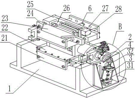
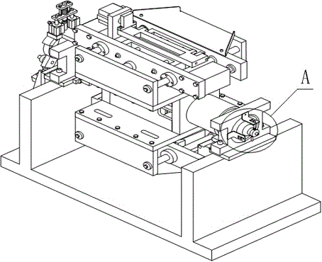
[0033] Such as figure 1 , figure 2 , Figure 5 , Figure 7 As shown, a lead parts casting equipment is characterized in that it includes a frame 1, a mold frame shaft 2 is arranged on the frame 1, and two sets of mold frames that are rotationally symmetrical along the mold frame shaft 2, and the mold frame shaft 2 is in the During work, one-way rotation is performed at a rotation angle of 90° / time. The middle part of the mold base shaft 2 is provided with a jacking cylinder 9, and the mold base shaft 2 is equipped with a one-way driving mechanism. 2 Connected formwork base plate 22, formwork base plate 22 is vertically provided with formwork guide post seat 21, and the upper end of formwork base plate 22 is symmetrically provided with two mold fixing plates 24 parallel to formwork guide post seat 21, one of the mold The upper end of the fixed plate 24 is provided with a waste sloping plate 23, and the two ends between the two mold fixed plates 24 are provided with a mold o...

Embodiment 2

[0035] Such as figure 1 , figure 2 , Figure 5 As shown, this embodiment is based on Embodiment 1, the joint bearing 32 is arranged in the axial direction of the cylinder I3, and the connection between the joint bearing 32 and the overrunning clutch 4 forms an included angle smaller than 180 degrees.

Embodiment 3

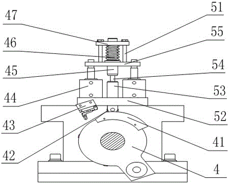
[0037] Such as Figure 1 to Figure 7 As shown, this embodiment is based on Embodiment 1 or Embodiment 2. The positioning mechanism includes a cylinder base 52 arranged on the bearing seat, two cylinders 44 are symmetrically arranged on the cylinder base 52, and the output ends of the cylinders 44 are provided with connections Plate 55, the center of connecting plate 55 is provided with spring mandrel 45, and spring mandrel 45 upper ends are provided with spring pressing plate 47, and spring mandrel 47 is sleeved with spring 46 between connecting plate 55 and spring pressing plate 47, and spring core The lower end of the shaft 47 is connected with a roller shaft 53 through a connecting screw rod 54. The movable end of the roller shaft 53 is provided with a roller 42. 4 equally divided star wheel-shaped parts on the side; the two ends of the spring pressing plate 47 are provided with bolts 51 to connect, and the bolts 51 pass through the through holes on the spring pressing plat...


PUM


Abstract

The invention relates to lead part casting equipment. The lead part casting equipment comprises a machine frame, wherein a mold base rotary shaft and two sets of mold bases are arranged on the machine frame, the mold bases are symmetrical about the mold base rotary shaft in a rotary mode, an ejection cylinder is arranged in the middle of the mold base rotary shaft, and a one-way drying mechanism is arranged on the mold base rotary shaft in a matched mode. By arranging two sets of molds, in one-circle rotation of the mold base rotary shaft, four stations work at the same time, lead parts can be cast twice, and therefore liquid lead casting efficiency is improved; furthermore, the vertically downward ejecting and discharging method is adaptable to automatic demolding of lead parts with almost any structures, lead part demolding is reliable, and fully-automatic production can be achieved. The lead part casting equipment overcomes the defects of existing fixed single-mold mold base structures that production efficiency is low, adaptability to lead part molds with complicated structures is poor, and automation degree is low.

Description

technical field [0001] The invention relates to the field of lead parts preparation, in particular to a casting equipment for lead parts. Background technique [0002] In the preparation process of lead parts, the casting body of lead parts usually has a frame, a lead melting furnace, a lead spoon, a mold, a mold base, a conveying device, a waste lifting device, a smoke hood and an electric control box, and the lead spoon is equipped with a heating device. , place the lead ingot in the lead melting furnace and heat it into molten lead, and the mold is used to cast the molten lead into shape. The mold is supported by the mold frame. For example, on the die-casting machine, the parts of the mold are combined and fixed according to certain rules and positions, and the part that enables the mold to be installed on the die-casting machine is called the mold frame. The mold frame is an integral part of the mold. It can be said that The skeleton of the whole set of mold is equippe...

Claims


Application Information

Patent Timeline
Patent Type & Authority Patents(China)
IPC IPC(8): B22D17/22B22D17/32B22D17/20
Inventor 王远强易波郑朝前
Owner 扬州金螳螂机械铸造有限公司
Learn More