Liftable supporting leg type elevator shaft construction platform and method

The technology of a construction platform and construction method is applied in the direction of house structure support, house structure support, house structure support scaffolding, etc., which can solve the trouble of hoisting and scaffolding steel pipes, the limited mechanical bearing capacity of scaffold steel pipes, and the stability of the frame body. To achieve the effect of fast construction, shortened construction period and improved construction efficiency

Active Publication Date: 2015-12-30
THE THIRD CONSTR & ENG OF CCFED
View PDF5 Cites 14 Cited by
  • Summary
  • Abstract
  • Description
  • Claims
  • Application Information

AI Technical Summary

Problems solved by technology

However, when constructing the shear walls of elevator shafts in high-rise and super high-rise buildings, because the inside of the elevator shaft is connected up and down, and the space is narrow, it not only brings various inconveniences to the construction personnel, but also brings greater safety hazards with the increase of floors.
In order to solve the above problems, the existing elevator shaft shear wall construction method is to build fastener type steel pipe scaffolding in the elevator shaft, and the construction personnel stand on the scaffold to construct the elevator shaft shear wall. However, for high-rise and super high-rise buildings Said that if the above method is used for construction, as the floor continues to rise, it is necessary to continuously increase and build new scaffolding. Not only is it more troublesome to hoist and build steel pipes for scaffolding, it will prolong the construction period and reduce construction efficiency, and the mechanical properties of steel pipes for scaffolding The bearing capacity is limited. When the height of the scaffold exceeds 50m, the steel pipe at the bottom of the scaffold will bear huge pressure, and the stability of the scaffold will deteriorate, posing safety hazards.

Method used


Image

  • Liftable supporting leg type elevator shaft construction platform and method
  • Liftable supporting leg type elevator shaft construction platform and method
  • Liftable supporting leg type elevator shaft construction platform and method

Examples


Embodiment Construction

[0023] In order to make the purpose, technical solution and advantages of the present invention clearer, the present invention will be further described in detail below in conjunction with the accompanying drawings and embodiments.

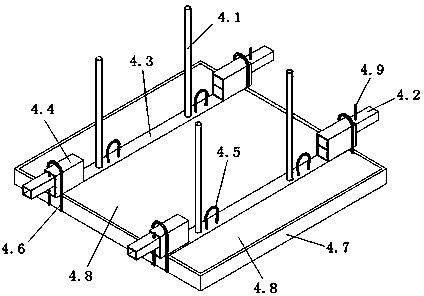
[0024] Embodiments of the invention: see figure 1 , a kind of liftable outrigger type elevator shaft construction platform of the present invention, comprises the construction platform 4 that is made up of outer frame 4.7, the beam 4.3 that is arranged in the outer frame 4.7, and the steel plate 4.8 that is laid on the outer frame 4.7 and beam 4.3, in A sleeve 4.4 is welded at both ends of the beam 4.3, and a slidable variable-section outrigger 4.2 is arranged inside the sleeve 4.4. For a structural schematic diagram of the variable-section outrigger, see Figure 5 . In order to prevent the variable-section outrigger 4.2 from moving, a bolt 4.9 is provided in the middle of the variable-section outrigger 4.2; a group of connecting rods 4.1 are ver...


PUM


Abstract

The invention discloses a liftable supporting leg type elevator shaft construction platform and method. The construction platform comprises an outer frame, cross beams arranged in the outer frame and a construction platform body consisting of steel plates laid on the outer frame and the cross beams and is characterized in that sleeves are welded to two ends of each cross beam, slidable variable-cross-section supporting legs are arranged in the sleeves, and a group of connecting rods is vertically arranged on each cross beam. Due to the fact that the construction platform is arranged on the structural beams, the height difference of the variable-cross-section supporting legs enable the construction platform to be lower than structural beam plates, reinforcement of an inner side formwork of an elevator shaft is facilitated, and concrete forming quality is ensured. Therefore, the liftable supporting leg type elevator shaft construction platform is simple in operation, quick and convenient to construct and safe and reliable in use, can be constantly lifted according to the height of a constructed building, can effectively improve construction efficiency and shorten a construction period and can be repeatedly used, and construction cost can be saved.

Description

technical field [0001] The invention relates to a construction platform and a construction method of a liftable outrigger type elevator shaft, which belong to the technical field of building construction. Background technique [0002] With the continuous improvement of today's architectural design level, the continuous development of construction technology and the improvement of the requirements for building functions, high-rise and super high-rise buildings continue to emerge. However, when constructing the shear walls of elevator shafts in high-rise and super high-rise buildings, because the inside of the elevator shaft is connected up and down, and the space is narrow, it not only brings various inconveniences to the construction personnel, but also brings greater safety hazards with the increase of floors. . In order to solve the above problems, the existing elevator shaft shear wall construction method is to build fastener type steel pipe scaffolding in the elevator s...

Claims


Application Information

Patent Timeline
Patent Type & Authority Applications(China)
IPC IPC(8): E04G3/28
Inventor 张杨钟佳
Owner THE THIRD CONSTR & ENG OF CCFED
Why Eureka
Try Eureka