A Rotation Modulation Radial Spherical Pure Electromagnetic Bearing

A technology of rotation modulation and magnetic bearings, applied to bearings, shafts and bearings, mechanical equipment, etc., can solve the problems of increasing the torsional bearing load of the flywheel, uneven magnetic air gap, uneven electromagnetic force, etc., and achieve the elimination of radial translation Effects of interference, improvement of detection accuracy, and good circumference uniformity

Inactive Publication Date: 2017-09-15
UNIV OF SCI & TECH BEIJING +1
View PDF11 Cites 0 Cited by
  • Summary
  • Abstract
  • Description
  • Claims
  • Application Information

AI Technical Summary

Problems solved by technology

However, when the rotor deflects, the magnetic air gap between the stator and rotor of the magnetic bearing is uneven, resulting in uneven electromagnetic force in the magnetic pole surface, thereby generating a torsional moment relative to the center of mass of the rotor, that is, the translation control produces an interference torque to the torsion control
The permanent magnet bias radial magnetic bearing described in Chinese Patent No. 201010256248.6 and 200710065049.5 and the radial magnetic bearing with pole shoes described in 201010226322. Uneven air gap, resulting in a large torsional negative torque, which increases the load on the torsional bearing of the flywheel, thereby reducing the control accuracy and control torque accuracy of the flywheel rotor, and the angle of the pole shoe is very small, which is prone to magnetic density saturation, and It will affect the uniformity of the magnetic density distribution along the circumference, which will indirectly lead to the reduction of control accuracy
In addition, if the existing magnetic levitation flywheel or magnetic levitation gyro is to realize its detection function as a sensitive component, it is often limited by the environmental disturbance torque, which leads to the reduction of the accuracy of the detection component.

Method used


Image

  • A Rotation Modulation Radial Spherical Pure Electromagnetic Bearing
  • A Rotation Modulation Radial Spherical Pure Electromagnetic Bearing
  • A Rotation Modulation Radial Spherical Pure Electromagnetic Bearing

Examples


Embodiment Construction

[0020] specific implementation plan

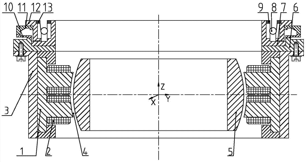
[0021] Such as figure 1 and figure 2 As shown, a rotary modulation radial spherical pure electromagnetic bearing mainly includes: four stator cores 1, coils 2, sleeves 3, air gaps 4, rotor 5, and stator mountings placed along the ±X and ±Y directions. Disc 6, rotation modulation rotor bearing sleeve 7, rotation modulation bearing 8, rotation modulation rotor lock nut 9, ultrasonic motor rotor 10, ultrasonic motor stator 11, rotation modulation stator bearing sleeve 12 and rotation modulation stator lock nut 13. Among them, the radial bearing coil 2 is wound on the two magnetic poles of each stator core 1, the radial inner side of the four stator cores 1 is the rotor 5, a radial magnetic air gap 4 is formed between the stator core 1 and the rotor 5, and the stator The radial outer side of the iron core 1 is the sleeve 3, the sleeve 3 is fixedly connected with the stator mounting plate 6 by screws, the axial outer side of the stator mount...


PUM


Abstract

The invention relates to a rotation-modulation radial spherical pure electromagnetic bearing which mainly comprises four stator cores, coils, sleeves, air gaps, rotors, a stator installation disk, a rotation-modulation rotor bearing sleeve, a rotation-modulation bearing, a rotation-modulation rotor lock nut, an ultrasonic motor rotor, an ultrasonic motor stator, a rotation-modulation stator bearing sleeve and a rotation-modulation stator lock nut, wherein the four stator cores are placed along the positive and negative X direction and the positive and negative Y direction. The stator of the radial spherical pure electromagnetic bearing is driven by an ultrasonic motor, so that the rotation of the stator is realized, a rotation-modulation function is realized, gyro drift caused by the rotation of a gyrorotor can be eliminated, and the detection precision during angular rate detection is greatly increased.

Description

technical field [0001] The invention relates to a non-contact radial magnetic suspension bearing, especially a spherical pure electromagnetic magnetic bearing with rotation modulation function, which can be used as non-contact support for rotating parts in small spacecraft, and is especially suitable for non-contact support of magnetic suspension sensitive gyroscopes . technical background [0002] With the development of aerospace technology, satellites, space stations and other spacecraft have higher and higher requirements for attitude control accuracy, and traditional mechanical momentum wheels can no longer meet the requirements. The magnetic levitation flywheel is supported by magnetic bearings, which eliminates the wear caused by mechanical bearings and improves the accuracy and stability of torque control. [0003] In the existing magnetic levitation flywheel or magnetic levitation control moment gyro structure, two degrees of freedom radial magnetic bearings are ge...

Claims


Application Information

Patent Timeline
Patent Type & Authority Patents(China)
IPC IPC(8): F16C32/04
Inventor 缪存孝赵航任元韩天胡纯刘强辛朝军张清东张立元
Owner UNIV OF SCI & TECH BEIJING
Why Eureka
Try Eureka