
Method and system for sensor fault diagnosis of EMU air brake control system

A sensor failure and air brake technology, applied in general control systems, control/regulation systems, test/monitoring control systems, etc., can solve the problems of slow sensor drift measurement deviation, unfavorable application, and high complexity, and improve fault diagnosis. The effect of high level, easy computer implementation, and low algorithm complexity

Active Publication Date: 2018-01-12
TSINGHUA UNIV +1
View PDF8 Cites 0 Cited by
  • Summary
  • Abstract
  • Description
  • Claims
  • Application Information

AI Technical Summary

Problems solved by technology

[0004] At present, the air brake control system mainly uses a simple over-limit alarm mechanism to judge whether the measured sensor is abnormal, or judges whether the sensor has a short circuit or open circuit based on the hardware circuit, and rarely involves the soft fault of these sensors themselves. diagnosis
In actual use, due to the influence of the complex and changeable external environment and the characteristics of the electronic device itself, the sensor usually has its own soft faults such as slow drift and measurement deviation.
Although these failures will not cause the failure of the braking system in a short period of time, they will have a negative impact on the performance of the braking system, thereby causing potential safety hazards to the braking system.
In addition, in the prior art, a method based on the combination of signal processing and pattern classification is also used for sensor fault diagnosis. However, this type of method has the disadvantages of difficult to obtain modeling data, poor real-time performance, and high complexity, which is not conducive to practical application.

Method used


Image

  • Method and system for sensor fault diagnosis of EMU air brake control system
  • Method and system for sensor fault diagnosis of EMU air brake control system
  • Method and system for sensor fault diagnosis of EMU air brake control system

Examples


Embodiment Construction

[0038] The implementation of the present invention will be described in detail below with reference to the accompanying drawings and embodiments, so as to fully understand how the present invention applies technical means to solve technical problems and achieve corresponding technical effects and implement them accordingly. The embodiments of the application and the features in the embodiments can be combined with each other under the premise of no conflict, and the technical solutions formed are all within the protection scope of the present invention.

[0039] The air brake system of the EMU mainly includes the air source system, the air brake control device, and the basic brake device. As the core component, the brake control unit BCU is usually divided into two parts: the electronic brake control unit EBCU and the pneumatic brake control unit PBCU. EBCU is the brake computer. PBCU mainly includes charging solenoid valve, exhaust solenoid valve, emergency valve, empty and heav...


PUM


Abstract

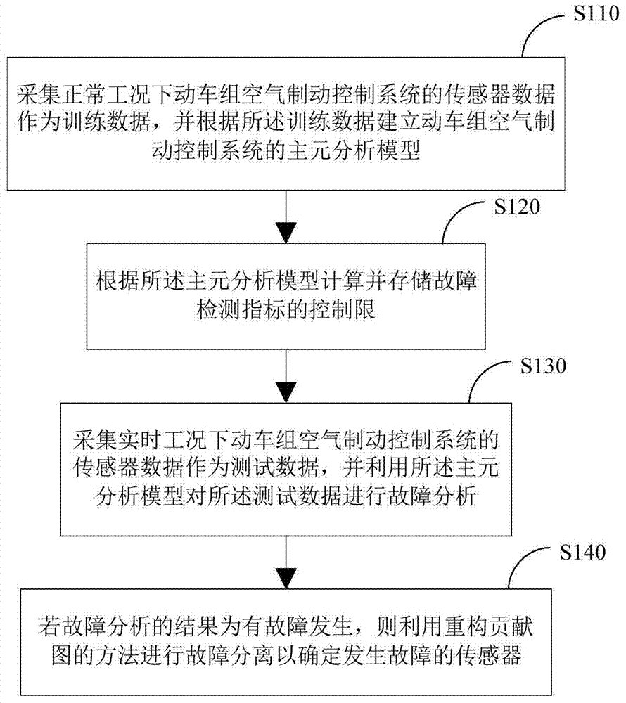
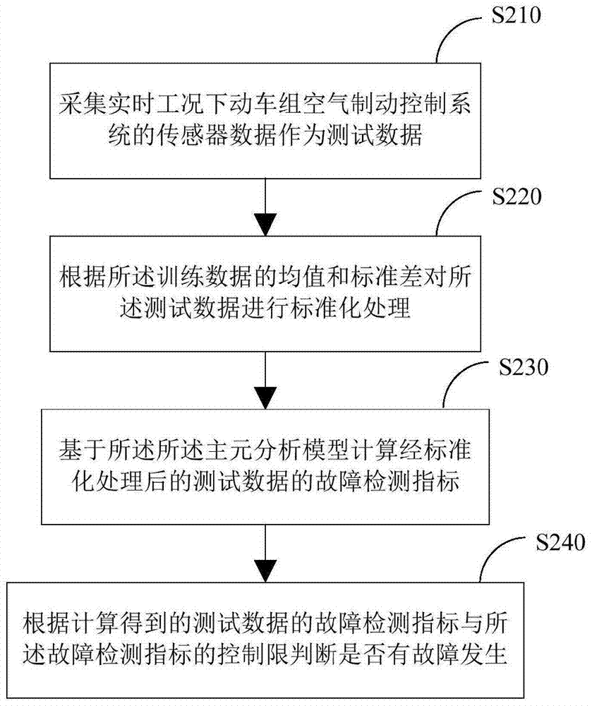
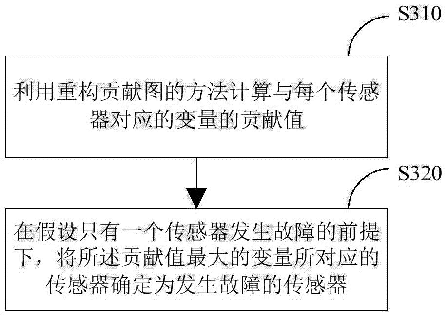
The invention discloses a sensor fault diagnosing method and system for an air braking control system of a motor train unit. The method comprises the steps that sensor data of the air braking control system of the motor train unit on the normal condition are collected as training data, and a principal component analysis model of the air braking control system of the motor train unit is built according to the training data; control limits of fault detection indexes are calculated and stored according to the principal component analysis model; sensor data of the air braking control system of the motor train unit on the real-time condition are collected as testing data, and fault analysis is performed on the testing data through the principal component analysis model; if a result of the fault analysis shows that a fault occurs, fault separation is performed through a contribution plot reconstruction method to determine a failed sensor. According to the sensor fault diagnosing method and system for the air braking control system of the motor train unit, the higher real-time performance is achieved, and meanwhile an algorithm is low in complexity and easy to achieve through a computer; the slow drift and deviation faults occurring in the sensors of the air braking control system of the motor train unit can be effectively diagnosed.

Description

Technical field [0001] The invention relates to the field of industrial monitoring and fault diagnosis, in particular to a method and system for sensor fault diagnosis of an air brake control system of an EMU. Background technique [0002] The air brake control system of the EMU mainly adopts the microcomputer-controlled direct electro-pneumatic brake method, and its core component is the brake control unit BCU. The main function of the BCU is to convert the brake commands issued by the driver's brake controller and the train brake control system through the charging solenoid valve and the exhaust solenoid valve (the two are collectively called the electro-pneumatic conversion valve, that is, the EP valve) or the emergency valve. For the corresponding pre-control pressure, the relay valve is controlled to generate the control pressure of the brake cylinder, and the basic braking device is controlled to apply and relieve the brake. Therefore, the performance of the BCU directly d...

Claims


Application Information

Patent Timeline
Patent Type & Authority Patents(China)
IPC IPC(8): G05B23/02
CPCG05B23/0224G05B2219/24033
Inventor 周东华何潇纪洪泉台秀华赛华松
Owner TSINGHUA UNIV
Learn More