Cooling method of battery pack and battery pack with cooling device

A technology of a cooling device and a cooling method, which is applied to secondary batteries, circuits, electrical components, etc., can solve the problems of thermal runaway, poor cooling effect, and low effective weight, and achieve the effect of preventing thermal runaway.

Active Publication Date: 2015-12-30
方乐同
View PDF11 Cites 19 Cited by
  • Summary
  • Abstract
  • Description
  • Claims
  • Application Information

AI Technical Summary

Problems solved by technology

[0005] Therefore, in the above-mentioned existing solutions, there are problems such as low effective weight, which leads to an increase in the weight of the battery pack; or poor cooling effect, which affects the life

Method used


Image

  • Cooling method of battery pack and battery pack with cooling device
  • Cooling method of battery pack and battery pack with cooling device
  • Cooling method of battery pack and battery pack with cooling device

Examples


Embodiment 1

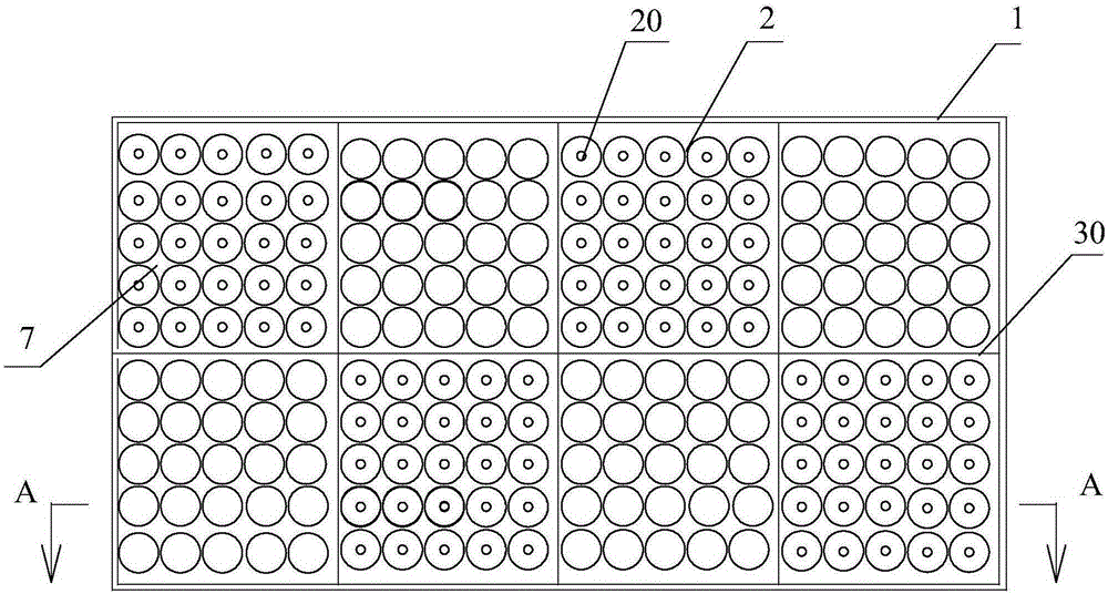
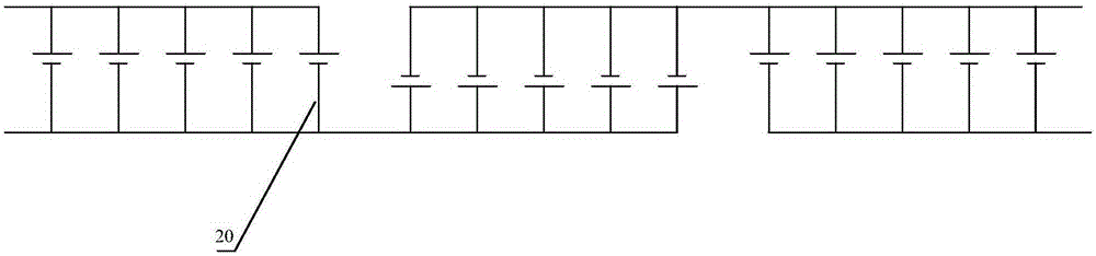
[0082] Embodiment 1. A battery pack with a cooling device, which includes a sealed casing 1, and in the inner cavity of the casing 1, a grid-shaped partition formed by criss-crossing partitions 30 (for example, Such as figure 1 The eight divisions mentioned above), one battery group 2 is set in each division, the battery group 2 with the positive pole upward and the battery group 2 with the negative pole upward are arranged alternately in the above division, and the battery group 2 passes through The main circuit conductors are connected in parallel and in series (such as image 3 said, note: the way of parallel series belongs to the conventional technology). The main circuit wire can be designed in an integrated form with the housing 1, which can simplify the structure more.

[0083] Remarks: In order to make the drawing clearer; the above main circuit wires are omitted in the drawing.

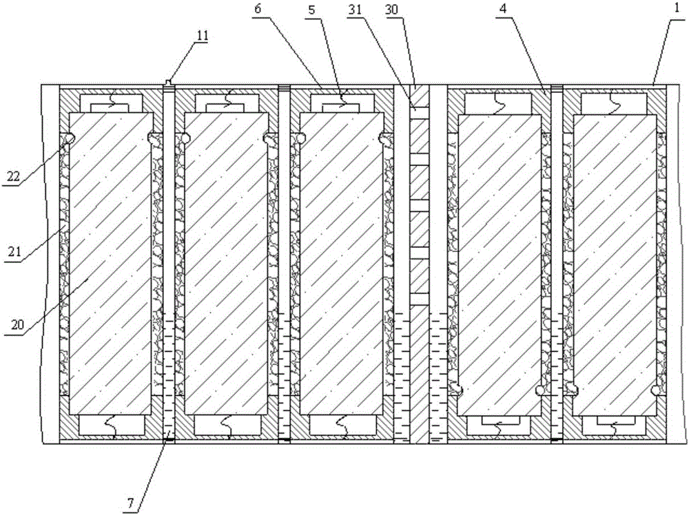
[0084] The specific structure of each battery group 2 is as follows:

[0085] Each b...

Embodiment 2

[0120] Embodiment 2. Combining several battery packs with cooling devices described in Embodiment 1:

[0121] When due to the needs of the installation layout, these several battery packs with cooling devices must be installed separately, when several battery packs are used together, a gas conduit 12 can be arranged on the upper part of the casing 1 of each battery pack, The lower part of the body 1 is provided with a liquid conduit 13 ; the cooling liquid vapor generated by the evaporation of the cooling liquid 7 flows through the gas conduit 12 , and the cooling liquid 7 flows through the liquid conduit 13 . In this way, the mutual flow of coolant vapor and coolant between the battery packs is realized. That is, the gas layer on the upper layer and the liquid layer on the lower layer in the casing 1 are connected through independent pipes, so as to ensure unimpeded communication between the gas and the cooling liquid.

[0122] The rest of the working methods are the same as...

Embodiment 3

[0123] Embodiment 3, when the battery pack is placed upright:

[0124] When the external layout requires that the battery pack must be placed vertically, the cooling medium (coolant 7) needs to submerge all the battery cells 20. Therefore, compared with Embodiment 1, the use of "wrapping the outer surface of the battery cells 20" can be cancelled. The absorbent layer 21".

[0125] The heat exchange of the cooling liquid 7 needs to be heated by natural convection, and it is difficult to obtain heating conditions for the deep battery cells 20. At this time, a gas circulation pump 8 can be added outside the battery pack, and the two ends of the gas circulation pump 8 are respectively connected to the casing The top and bottom of the inner cavity of 1 are connected; thus, the gaseous medium in the upper layer is pumped to the lowermost layer for circulation, and the overall uniform gas-liquid coexistence state in the shell 1 can be maintained to provide uniform temperature perform...


PUM


Abstract

The invention discloses a battery pack with a cooling device and further discloses a cooling method of the battery pack. The cooling method comprises the following steps: when the temperature of a battery cell in a shell rises, cooling fluid around the battery cell is immediately boiling and evaporated, and latent heat absorbed during evaporation can realize the cooling of the battery cell; the produced cooling fluid vapor is distributed in the inner chamber of the shell, such that the internal pressure of the inner chamber of the shell rises, partial cooling fluid in the inner chamber of the shell is condensed, the internal temperature of the shell rises and temperature corresponding to new vapor pressure is formed in the shell; when the temperature of the battery cell or a cooling part in the shell drops, the cooling fluid vapor around the battery cell or the cooling part is condensed to release latent heat and the condensation of the cooling fluid causes the pressure of the inner chamber of the shell to drop, such that partial cooling fluid is evaporated, the internal temperature of the shell drops and temperature corresponding to new vapor pressure is formed in the shell.

Description

technical field [0001] The invention relates to a cooling method for a battery pack and a corresponding battery pack with a cooling device. Background technique [0002] At present, the cooling methods of the existing battery packs include liquid cooling, airflow cooling, phase change medium cooling, and heat pipe cooling. Among these methods, the airflow cooling structure is the simplest, but there are problems such as small cooling capacity, large temperature difference between battery cells, impact on battery life, and limited discharge power. Although it can be compensated by adjusting battery materials, it mostly results in loss of power storage Capacity comes at a cost. [0003] Liquid cooling requires a complex circulation loop, which increases the weight of the system a lot. After the battery pack is grouped, the monomers account for only about 50%. In the current situation where the battery weight ratio is insufficient, precious weight is lost. [0004] The coolin...

Claims


Application Information

Patent Timeline
IPC IPC(8): H01M10/613H01M10/615H01M10/617H01M10/625H01M10/6552
CPCY02E60/10
Inventor 方乐同方国平
Owner 方乐同
Why Eureka
Try Eureka