Eureka AIR delivers breakthrough ideas for toughest innovation challenges, trusted by R&D personnel around the world.

Aseismic connection device for connecting a panel to a beam

A connecting device and connecting technology, applied in the direction of building components, building types, walls, etc., can solve the problem of not being able to guide relative displacement, and achieve the effect of avoiding high shear force

Inactive Publication Date: 2015-12-30
I·贝奇
View PDF6 Cites 0 Cited by
  • Summary
  • Abstract
  • Description
  • Claims
  • Application Information

AI Technical Summary

Problems solved by technology

The above device is not intended to hold two structures together and cannot guide the relative displacement of the two structures in a direction perpendicular to the axis of the device

Method used


Image

  • Aseismic connection device for connecting a panel to a beam
  • Aseismic connection device for connecting a panel to a beam
  • Aseismic connection device for connecting a panel to a beam

Examples


Embodiment Construction

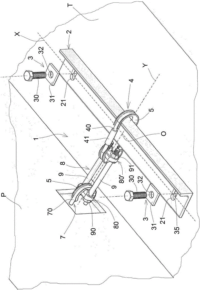
[0027] With reference to the drawings, a connection device according to the present invention is disclosed, which is generally indicated by the reference numeral 1.

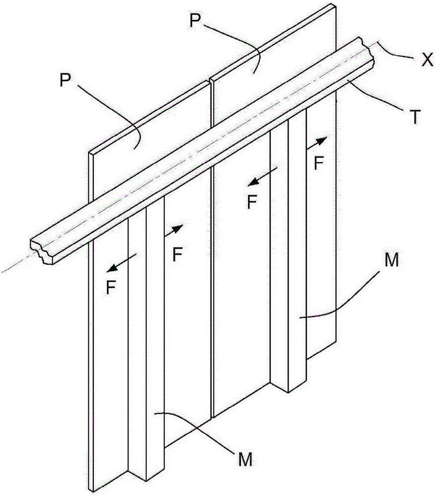
[0028] figure 2 A beam T and a panel P adapted to be connected to the beam T by the connecting device 1 are shown. In the following description, the terms "transverse" and "longitudinal" refer to the transverse and longitudinal directions of the beam T, respectively.

[0029] When connecting the panel P to the beam, the inner surface of the panel abuts against the longitudinal edge of the beam, and the upper surface of the beam is perpendicular to the inner surface of the panel.

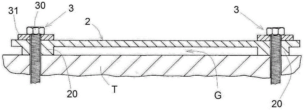
[0030] The connecting device 1 comprises a dispersing element 2 which is shaped as a deformable rod in cross section and has a longitudinal axis X. The dispersion element 2 is fixed to the beam T so that the longitudinal axis X of the dispersion element is parallel to the longitudinal axis of the beam.

[0031] For illustrative purposes, the d...


PUM


Abstract

A seismic connection device (1) for connecting a panel (P) to a beam (T), comprising a dissipating element (2) with longitudinal axis (X) fixed to the beam (T) only in correspondence of its longitudinal ends, a sliding connector (4) slidingly mounted on the dissipating element (2) in such manner to slide along the longitudinal axis (X) of the dissipating element, a fixed connector (7) fixed to the panel (P), a tensioning element (8) disposed between the fixed connector (7) and the sliding connector (4) to allow for a linear displacement of the fixed connector (7) towards the sliding connector (4). Said panel (P) is adapted to move with respect to the beam (T) in the direction of the longitudinal axis (X).

Description

Technical field [0001] This patent application for industrial invention relates to a seismic connection device for connecting panels to beams. Background technique [0002] Figure 1 is a schematic diagram of a part of the building structure, the building structure includes a pillar (M) fixed to the ground, a beam (T) arranged on the pillar (M), and a beam (T) fixed on the ground and the beam (T) The panel (P), the pillar (M) and the beam (T) form a support structure, and the panel (P) forms a side wall supported by the support structure. [0003] Various systems for fixing the panel (P) to the beam (T) are known. However, known types of fixing systems generally do not guarantee seismic performance. [0004] In fact, the pillar (M) tends to vibrate in an earthquake due to being fixed to the ground. The most dangerous vibration is the vibration of the pillar (M) in the direction of the arrow (F) shown in the figure, which arrow (F) is substantially parallel to the longitudinal axis ...

Claims


Application Information

Patent Timeline
IPC IPC(8): E04B2/88E04H9/02
CPCE04B2/94E04H9/021E04B1/38E04B1/92
Inventor I·贝奇F·福雷西
Owner I·贝奇
Why Eureka
Eureka Blog
Learn More