
High-pressure nitrogen gas power ring road system

A high-pressure nitrogen, compressed nitrogen technology, applied in pipeline systems, gas/liquid distribution and storage, mechanical equipment, etc., can solve the problems of difficult test data analysis, loss of drag reduction effect, structural damage, etc., to ensure the effect of safe operation.

Inactive Publication Date: 2014-10-22
CHINA PETROLEUM & CHEM CORP +2
View PDF5 Cites 0 Cited by
  • Summary
  • Abstract
  • Description
  • Claims
  • Application Information

AI Technical Summary

Problems solved by technology

However, since the pump takes a certain amount of time from startup to stabilization, and the pressure and flow continue to fluctuate during the process, it will bring great difficulties to the analysis of test data.
In addition, due to the own characteristics of the drag reducer product, its structure will be damaged under the high-speed shearing action of the pump, thus losing the drag reducing effect

Method used


Image

  • High-pressure nitrogen gas power ring road system
  • High-pressure nitrogen gas power ring road system
  • High-pressure nitrogen gas power ring road system

Examples


Embodiment 1

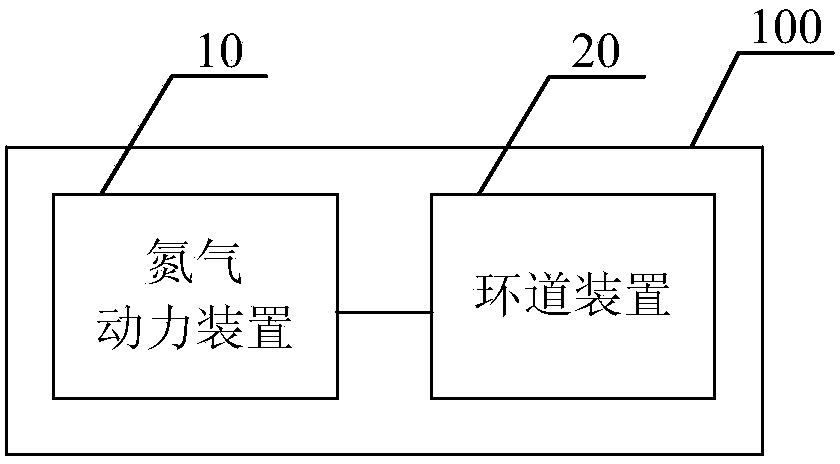
[0045] figure 1 A schematic structural diagram of a high-pressure nitrogen power loop system according to an embodiment of the present invention is shown. like figure 1 As shown, the high-pressure nitrogen power loop system 100 mainly includes a nitrogen power device 10 and a loop device 20 . The nitrogen power device 10 is used to provide high-pressure nitrogen for the loop device 20 as a power source for controlling the pressure to start, and the oil in the loop device 20 flows in the loop under the driving action of the high-pressure nitrogen.

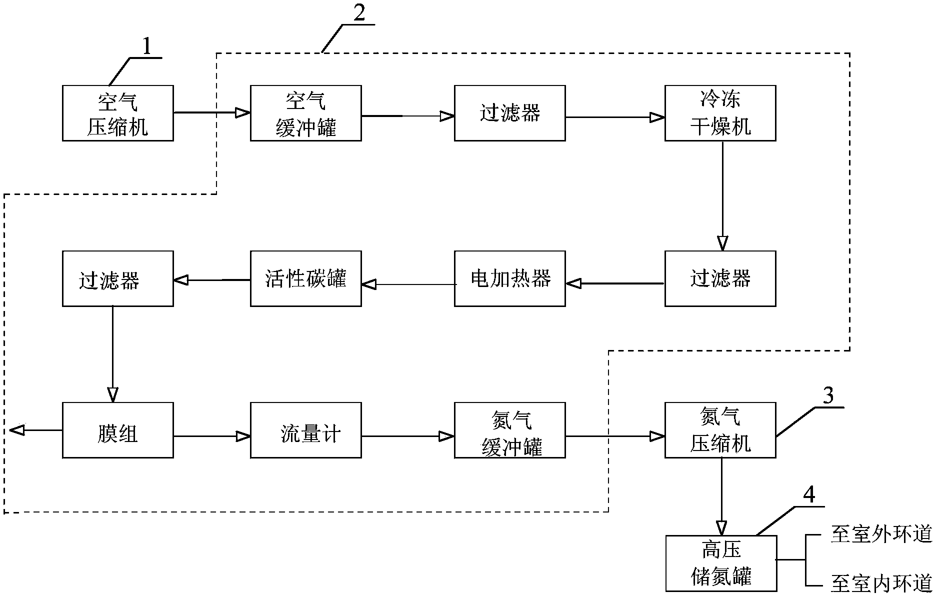
[0046] like figure 2 As shown, in this embodiment, the nitrogen power device 10 mainly includes: an air compressor 1 , a membrane nitrogen generating unit 2 , a nitrogen compressor 3 and a high-pressure nitrogen storage tank 4 .

[0047] Among them, the air compressor 1 is used for compressing air. The membrane nitrogen making unit 2 is connected with the air compressor 1, and is used to separate oxygen and nitrogen from the ...


PUM


Abstract

The invention relates to a high-pressure nitrogen gas power ring road system. The system comprises a nitrogen gas power device and a ring road device, wherein the nitrogen gas power device is used for providing compressed nitrogen gas; the ring road device is connected with the nitrogen gas power device and comprises a ring road and an oil storage device. Oil products in the oil storage device flow in the ring road under the driving action of the compressed nitrogen gas. According to the high-pressure nitrogen gas power ring road system, the high-pressure nitrogen gas serves as a power source of a restarting pipeline, and a stable pressure head can be provided for the restarting pipeline, and meanwhile it can be guaranteed that test chemicals are safely used.

Description

technical field [0001] The invention relates to the field of crude oil pipeline experiments, in particular to a high-pressure nitrogen power loop system. Background technique [0002] Most of my country's crude oil is oil with high wax content. If the temperature of the crude oil is low, the wax crystals in the crude oil will gradually precipitate. When the precipitated wax crystals reach a certain concentration, a spatial grid structure will be formed between the wax crystals, which will show a complex high-coagulation and high-viscosity non-Newtonian fluid flow. Variation properties. [0003] At present, most of the waxy crude oil adopts the pipeline transportation process of heating transportation. Although heating transportation is an effective measure for high-point and high-viscosity crude oil, the corresponding operation and investment costs are also high. At the same time, during the operation of the hot oil pipeline, accidents will inevitably occur. After stoppin...

Claims


Application Information

Patent Timeline
Patent Type & Authority Applications(China)
IPC IPC(8): F17D1/12F17D3/01
Inventor 曹旦夫吴杰成旭霞姜瑞罗倪广地王德治贾邦龙林森尤金龙黄迎峰张一丁杨辉庄君苏航
Owner CHINA PETROLEUM & CHEM CORP
Learn More