
Spindle drive for adjusting elements of motor vehicles

A technology for adjusting components and drives, which is applied to vehicle components, transmissions, wing and fan components, etc., to achieve uniform force distribution

Active Publication Date: 2019-06-21
博泽(哈尔施塔特)汽车零部件有限公司
View PDF5 Cites 0 Cited by
  • Summary
  • Abstract
  • Description
  • Claims
  • Application Information

AI Technical Summary

Problems solved by technology

[0008] A disadvantage of known spindle drives is the fact that a weight-reduced design of the housing is only possible within narrow limits due to the load associated with the torsional resistance.

Method used


Image

  • Spindle drive for adjusting elements of motor vehicles
  • Spindle drive for adjusting elements of motor vehicles
  • Spindle drive for adjusting elements of motor vehicles

Examples


Embodiment Construction

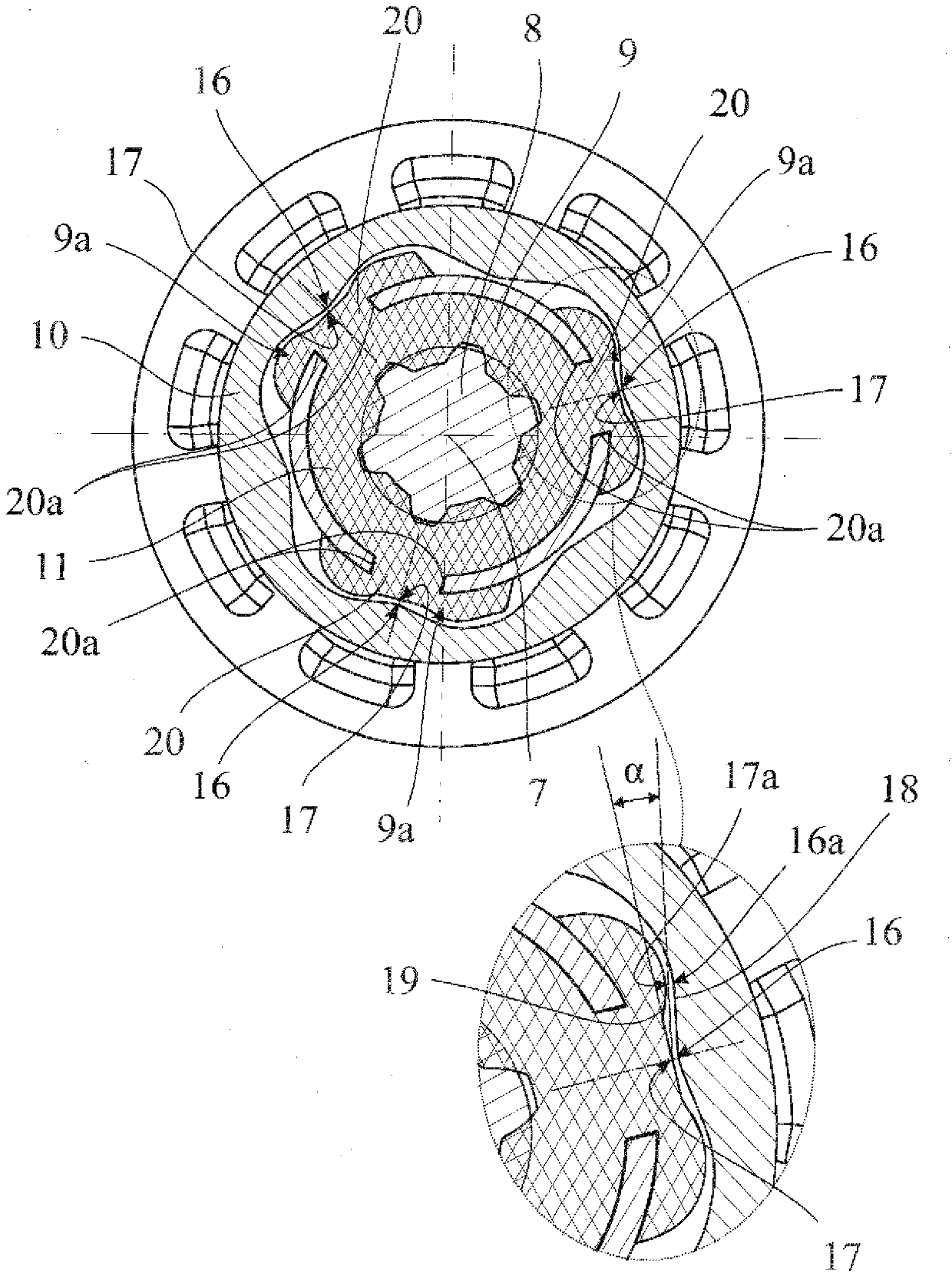
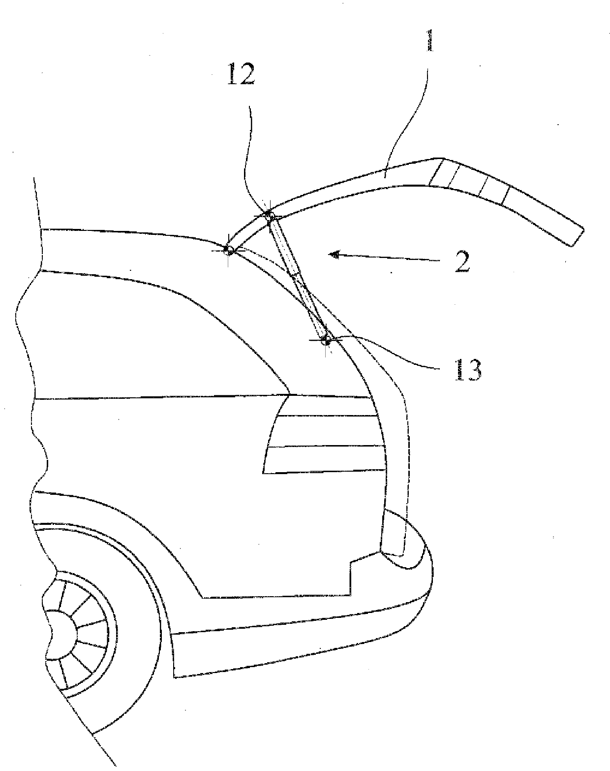
[0026] The spindle drive shown in the figure is used for motorized adjustment of an adjusting element 1 designed as a rear lid of a motor vehicle. As will be explained in more detail below, other fields of application of the proposed spindle drive are conceivable.

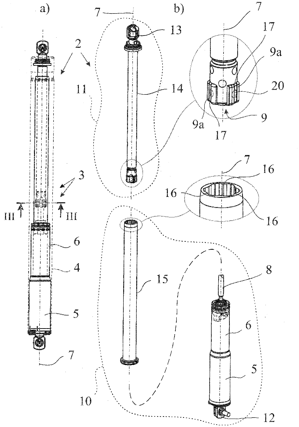
[0027] The spindle drive is conventionally equipped with a drive unit 2 and a spindle-spindle nut transmission 3 downstream of the drive unit 2 for generating the linear drive movement. In this case, the drive unit 2 has a here and preferably tubular and in particular one-piece drive unit housing with the drive motor 5 therein as well as an intermediate transmission 6 downstream of the drive motor 5 in terms of drive technology. Depending on the design of the drive motor, the intermediate gear 6 can also be omitted.

[0028] This results in a particularly slim design, in that the drive unit 2 and the spindle-spindle nut drive 3 are arranged one behind the other on the geometric spindle axis 7 .

[0029] In this r...


PUM


Abstract

Disclosed herein is a spindle drive for an adjustable element of a motor vehicle, wherein a drive unit and a spindle / spindle nut mechanism arranged downstream of the drive unit in the drivetrain, for generating linear drive movements are provided, wherein the spindle / spindle nut mechanism has a spindle and a spindle nut meshing with the spindle, wherein the spindle drive has two drive portions which run telescopically inside one another during a motorized adjustment, wherein the spindle is assigned to one drive portion and the spindle nut is assigned to the other drive portion wherein the two drive portions are coupled in a torque-transmitting manner to provide an antitwist safeguard.

Description

technical field [0001] The invention relates to a spindle drive for an adjusting element of a motor vehicle. Background technique [0002] The term "tuning element" is currently to be understood in a broad sense. These include, for example, rear lids, trunk lids, engine hoods, side doors, cargo lids, lift-off roofs, etc. of motor vehicles. The following areas of application for the motorized adjustment of the rear lid of a motor vehicle are in the foreground. This should not be construed as limiting. [0003] In the context of the motorized manipulation of the rear cover, spindle drives have proven suitable in recent years. Currently, high compactness as well as low weight are in the foreground. [0004] The known spindle drive (DE 20 2005 000 559 U1) from which the present invention is based generally has two drive sections, one of which is associated with the spindle and the other with the spindle nut engaging the spindle couplet. [0005] A coupling for deriving a l...

Claims


Application Information

Patent Timeline
Patent Type & Authority Patents(China)
IPC IPC(8): F16H25/20E05F15/611
CPCF16H25/20B60J5/101E05F15/611E05F15/622E05Y2900/546F16H2025/204
Inventor U.菲舍尔C.萨克斯施泰特
Owner 博泽(哈尔施塔特)汽车零部件有限公司
Learn More