Rotating shaft bending die

A bending die and rotating shaft technology, applied in metal processing equipment, forming tools, manufacturing tools, etc., can solve problems such as easy jamming of the upper die and excessive deformation of parts

Inactive Publication Date: 2016-01-06
CHONGQING YUKUNLONG METALLURGICAL MATERIAL CO LTD
View PDF0 Cites 5 Cited by
  • Summary
  • Abstract
  • Description
  • Claims
  • Application Information

AI Technical Summary

Problems solved by technology

[0003] The present invention intends to provide a rotating shaft bending die using a floating lower die to solve the problem of excessive deformation of parts or easy jamming of the upper die due to excessive stamping pressure of the upper die

Method used


Image

  • Rotating shaft bending die

Examples


Embodiment Construction

[0010] The present invention will be described in further detail below by means of specific embodiments:

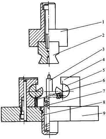
[0011] The reference numerals in the accompanying drawings of the description include: upper mold base 1, upper mold 2, lower mold 3, support plate 4, rotating support plate 5, set screw 6, compression spring 7, spring support 8, lower mold base 9.

[0012] The embodiment is basically as attached figure 1 Shown: the rotating shaft bending die of the present embodiment, the upper mold base 1 is cuboid and is integrally formed with the mold handle at its upper part, and the lower part of the upper mold base 1 is connected with a vertical upper mold 2 by screws, and the upper mold base The outer periphery of 2 has a ring-shaped V-shaped groove.

[0013] The lower mold base 9 is located directly below the upper mold base 1, and the upper part of the lower mold base 9 has a vertical installation groove, and a spring support is provided in the installation groove, and the stag...


PUM


Abstract

The invention discloses a rotating shaft bending die adopting a floating lower die body. The problem that a part is excessively deformed or an upper die body is prone to being jammed due to the fact that the impact force of the upper die body is too large can be solved. The rotating shaft bending die comprises an upper die seat and the upper die body mounted on the lower portion of the upper die seat, wherein the upper die body can move up and down; a lower die seat is located under the upper die seat, a vertical mounting groove is formed in the upper portion of the lower die seat, and a pressure spring is arranged in the mounting groove. The lower end of the pressure spring is fixed to the bottom of the mounting groove, the upper end of the pressure spring extends out of the mounting groove, and the floating lower die body is arranged in the middle of the pressure spring; a circle of annular table is arranged on the periphery of the lower die body, the upper end of the pressure spring is fixed to the annular table, and the diameter of the annular table is larger than the aperture of the mounting groove; a convex column is arranged on the top of the lower die body, the upper portion of the convex column is a spherical surface, a stamping groove is formed in the bottom of the upper die body, and the stamping groove and the convex column are matched to bend parts.

Description

technical field [0001] The invention relates to the technical field of bending dies, in particular to a rotating shaft bending die. Background technique [0002] Bending is a stamping process that bends the blank into a certain angle through a mold and a press according to the shape of the part, and a workpiece of a certain shape. The bending forming process is widely used in automobile panels, motorcycle bracket components, foot bracket parts, pipes, sheets, etc. The existing bending dies often have the following disadvantages: when forming, the forming is completed by directly stamping the blank on the lower die through the upper die, usually the lower die is fixed, and sometimes the downward punching force of the upper die will be greater , and after reaching the stamping, it is easy to get stuck in rigid contact with the blank and the lower die, which not only causes excessive deformation of the parts, but also affects the molding quality, and the upper die is prone to ...

Claims


Application Information

Patent Timeline
Patent Type & Authority Applications(China)
IPC IPC(8): B21D37/10
Inventor 罗静
Owner CHONGQING YUKUNLONG METALLURGICAL MATERIAL CO LTD
Why Eureka
Try Eureka