Die for multi-hole machining of aluminum template

A technology of hole processing and aluminum template, which is applied in the field of aluminum template porous processing molds, can solve the problems of multiple positioning times, the influence of product processing accuracy, and large punching force of punching punches, etc., to achieve improved performance, improved service life, and extended use. The effect of longevity

Inactive Publication Date: 2017-02-15
湖北森峰铝模科技有限公司
View PDF7 Cites 3 Cited by
  • Summary
  • Abstract
  • Description
  • Claims
  • Application Information

AI Technical Summary

Problems solved by technology

[0003] In the deep processing of aluminum profiles, installation holes of different specifications need to be punched on different positions of the aluminum profiles for the porous and long strips of industrial aluminum profiles. According to the current traditional processing method, the holes are punched one by one, and there are the following problems: 1. Work efficiency Low; 2. It is necessary to continuously adjust the angle of the profile according to the punching position, and the number of positioning times is high, which affects the processing accuracy of the product; 3. The position accuracy of the holes punched on the aluminum formwork directly affects the performance of the aluminum formwork. The method of punching holes one by one The position accuracy is low; 4. The wall formwork is a product that needs to be mass-produced. The material is 6061-T6 extruded aluminum alloy profile. The accuracy of the distance has become a problem that must be solved in processing; 5. The punching force of the traditional processing method is relatively large, and the punching die is easy to be damaged.

Method used


Image

  • Die for multi-hole machining of aluminum template
  • Die for multi-hole machining of aluminum template
  • Die for multi-hole machining of aluminum template

Examples


Embodiment Construction

[0027] The present invention will be further described below in conjunction with accompanying drawing:

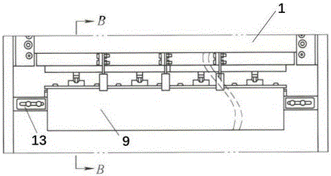
[0028] Such as figure 1 As shown, an aluminum template porous processing mold includes an upper mold fixing plate 1 and a lower mold fixing plate 2 arranged up and down, which are respectively used to fix the upper mold 5 and the lower mold 6, and the left and right ends of the lower mold fixing plate 2 are provided with positioning Block 13.

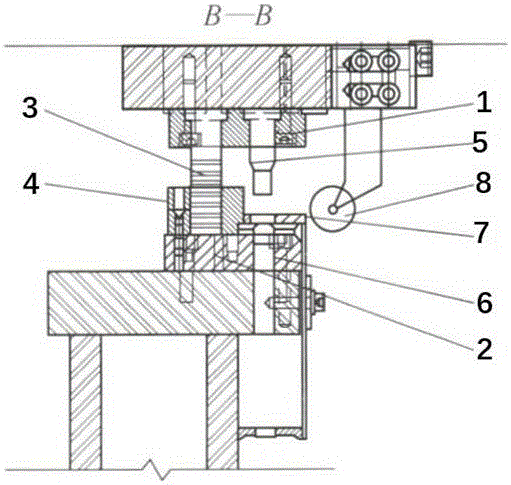
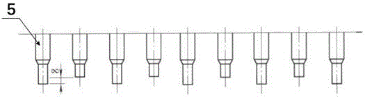
[0029] Such as figure 2 As shown, in order to ensure that the mold guides the mold stroke with precise positioning, the left part of the upper mold fixing plate 1 is vertically installed with a plurality of guide pillars 3, and the lower mold fixing plate 2 directly below the bottom of each guide pillar 3 A guide sleeve 4 matching the guide post 3 is arranged on the top; in order to realize the cutting edge at the bottom of the upper die 5 to punch the workpiece 9, a plurality of upper dies 5 are installed in the middle of the upp...


PUM

PropertyMeasurementUnit
thicknessaaaaaaaaaa

Abstract

The invention discloses a die for multi-hole machining of an aluminum template. The die comprises an upper die fixing plate and a lower die fixing plate which are arranged up and down. Guide columns, a plurality of upper die bodies and a rubber pressing roller are installed on the upper die fixing plate. Guide sleeves, lower die bodies and a discharge plate are installed on the lower die fixing plate. According to a product machined through the die, the hole tolerance between a hole formed in the head of the product and a hole formed in the tail of the product can be controlled within + / -0.4mm, the precision requirement for parts is met, and the usability is greatly improved; meanwhile, the upper die bodies are divided into two groups for operation in two batches, the total stamping force is decreased by half, the service life of the upper die bodies is prolonged, and high economical efficiency and energy conservation are achieved; furthermore, double oblique surfaces are designed on the edge of each upper die body, the stamping force is greatly decreased, a smooth hole can be obtained, and the discharging force is reduced almost to zero; and the guide columns have a self-lubrication function, abrasion caused by dry friction between the guide columns and the corresponding guide sleeves is avoided, the service life of the whole die is prolonged, and the use requirement of long-service-life and high-precision dies are met.

Description

technical field [0001] The invention belongs to the technical field of moulds, and in particular relates to a mold for processing aluminum template holes. Background technique [0002] Since the aluminum alloy formwork system was born in the United States in 1962, it has a history of nearly 50 years of application. It has been widely used in the buildings of developed countries such as the United States and Canada, as well as emerging industrial countries such as Mexico, Brazil, Malaysia, South Korea, and India. In the process of promotion and use, countries have also accumulated a lot of experience in the design, manufacture, application and construction of aluminum formwork. [0003] In the deep processing of aluminum profiles, installation holes of different specifications need to be punched on different positions of the aluminum profiles for the porous and long strips of industrial aluminum profiles. According to the current traditional processing method, the holes are ...

Claims


Application Information

Patent Timeline
Patent Type & Authority Applications(China)
IPC IPC(8): B21D28/34B21D37/18B21D37/12B21D37/01
CPCB21D28/34B21D37/01B21D37/12B21D37/18
Inventor 徐长锋
Owner 湖北森峰铝模科技有限公司
Why Eureka
Try Eureka