Intelligent steam hydrophobic valve

A steam trap and steam technology, applied in steam traps, mechanical equipment, etc., to achieve high heat exchange efficiency and ensure normal operation

Inactive Publication Date: 2016-01-06
YINGQIAO MACHINERY MFG
View PDF6 Cites 3 Cited by
  • Summary
  • Abstract
  • Description
  • Claims
  • Application Information

AI Technical Summary

Benefits of technology

This new design improves upon current methods for monitoring and controlling the performance of an evaporative coolers (ECLs). It allows direct measurement of both pressures or temperatures during its operations without requiring complicated equipment like sensors that are expensive or difficult to maintain overtime. Additionally, this technology helps prevent accidents caused by excessively high levels of water vapour inside the ECL's tank due to malfunctions such as leaks or damaged pipes. Overall, it provides technical benefits including improved accuracy, ease-of-use feature, automated process optimization capabilities, enhanced safety measures, etc., leading to better energy utilization rates while ensuring optimal operating conditions within the ELC.

Problems solved by technology

The technical problem addressed in this patents relates to prevention of leakages from steaming traps due to excessive moisture buildup caused by high temperatures during startup. Current methods require manually checking each part separately before starting work with these devices, which makes them difficult to manage and troublesome at different times throughout their lifespan.

Method used


Image

  • Intelligent steam hydrophobic valve
  • Intelligent steam hydrophobic valve
  • Intelligent steam hydrophobic valve

Examples


Embodiment Construction

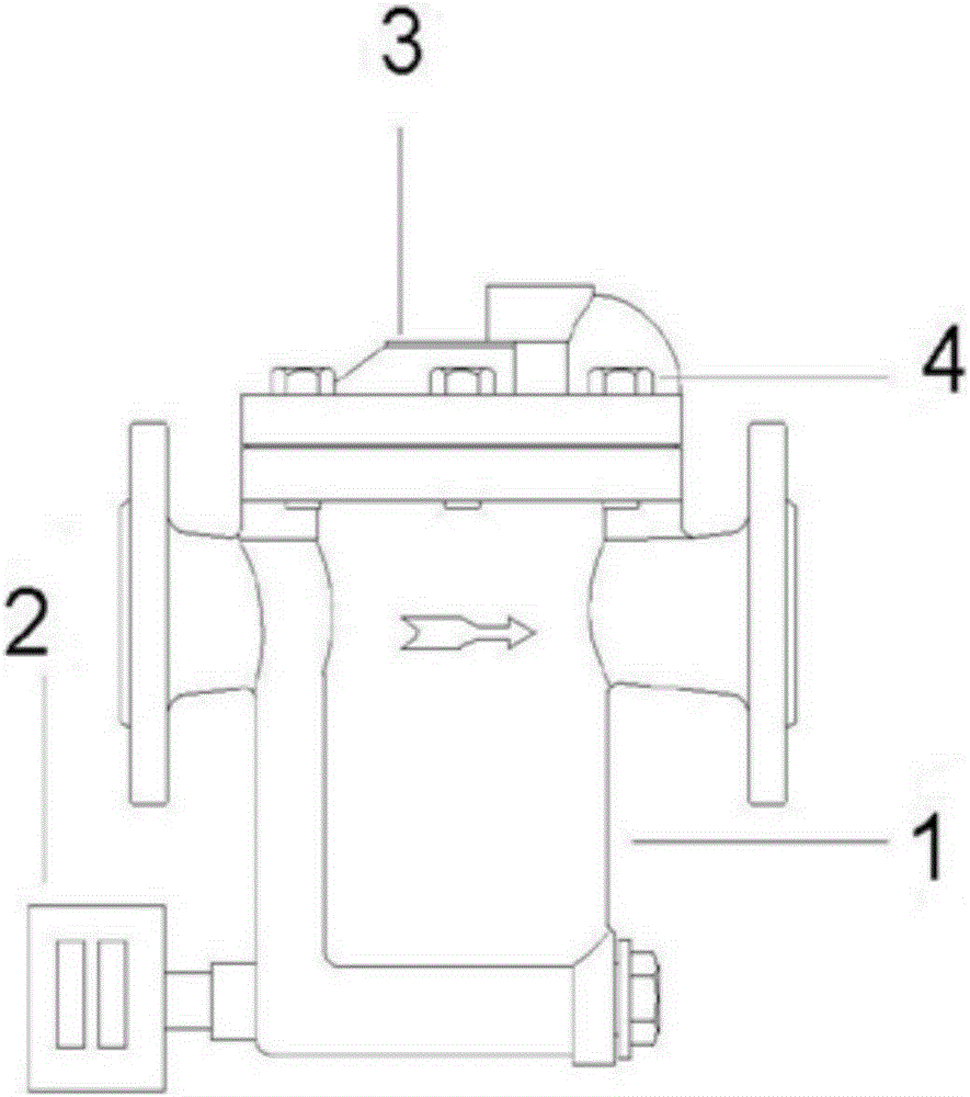
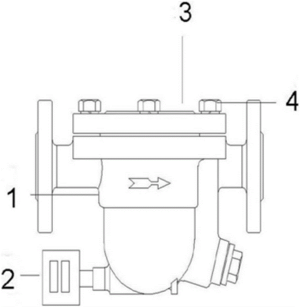
[0020] The following embodiments will further illustrate the present invention in conjunction with the accompanying drawings.

[0021] see Figures 1 to 7 , the embodiment of the present invention is provided with a valve body 1, a valve cover 3, bolts and nuts 4, an intelligent device 2, a control circuit 5, a communication module 6 and a computer 7; the intelligent device 2 is provided with a pressure sensor 21, a temperature sensor 22, a pressure The signal amplifier 23, the temperature signal amplifier 24, the digital display circuit 25 and the alarm circuit 26; the pressure sensor 21 and the temperature sensor 22 are arranged in the lower part of the valve body 1 to detect the pressure and temperature of the condensed water in the lower part of the valve body 1, and the pressure sensor 21 The output end of the temperature sensor 22 is connected to the input end of the pressure signal amplifier 23, the output end of the pressure signal amplifier 23 is connected to the inpu...


PUM


Abstract

The invention relates to a steam hydrophobic valve, in particular to an intelligent steam hydrophobic valve. The intelligent steam hydrophobic valve is provided with a valve body, a valve deck, bolts and nuts, an intelligent device, a control circuit, a communication module and a computer. The intelligent device is provided with a pressure sensor, a temperature sensor, a digital display circuit and an alarm circuit. The pressure sensor and the temperature sensor are arranged on the lower portion of the valve body. The output end of the pressure sensor is connected with the input end of a pressure signal amplifier. The output end of the pressure signal amplifier is connected with the input end of the control circuit. The output end of the temperature sensor is connected with the input end of a temperature signal amplifier. The output end of the temperature signal amplifier is connected with the input end of the control circuit. The output end of the control circuit is connected with the input end of the digital display circuit, the input end of the alarm circuit and the input end of the communication module. The output end of the communication module is connected with the computer. By arranging the pressure and temperature sensors, the digital display circuit and the alarm reminding device, multiple paths of or multiple steam hydrophobic valves can be use for collecting and transmitting data in a wired or wireless mode through a controller, and then the steam hydrophobic valves are in networking with the computer or a mobile phone for digital management.

Description


Claims


Application Information

Patent Timeline
Owner YINGQIAO MACHINERY MFG
Why Eureka
Try Eureka