Uniform heat radiation structure

A technology of uniform heat dissipation and heat dissipation fins, applied in heat exchange equipment, lighting and heating equipment, etc., can solve the problems of low heat dissipation efficiency, no space utilization, and reduced efficiency, and achieve uniform heat dissipation, improved heat dissipation efficiency, and multiple heat dissipation spaces Effect

Inactive Publication Date: 2016-01-06
WUXI JIAMEIDA RUBBER & PLASTIC EQUIP
View PDF0 Cites 0 Cited by
  • Summary
  • Abstract
  • Description
  • Claims
  • Application Information

AI Technical Summary

Problems solved by technology

[0002] As we all know, too high temperature will cause certain damage to most non-high temperature equipment, such as LED, solar battery or computer CPU, etc., because the temperature itself will rise during operation. The efficiency will drop, and the equipment will burn out. In this case, radiators are often used as auxiliary equipment to dissipate heat. Radiators are generally composed of heat dissipation structures and other auxiliary structures. In the prior art, heat dissipation fins in heat dissipation structures are mostly rectangular. Moreover, the size of each heat sink is the same, which does not make good use of the space, resulting in a small heat dissipation area of ​​the heat sink and low heat dissipation efficiency. When the heat sink area is large, the surrounding environment of the heat dissipation structure is different, such as the heat dissipation structure There is a shield on one side, and the other side is more ventilated, which will cause uneven heat dissipation of the heat sink

Method used


Image

  • Uniform heat radiation structure
  • Uniform heat radiation structure
  • Uniform heat radiation structure

Examples


Embodiment 1

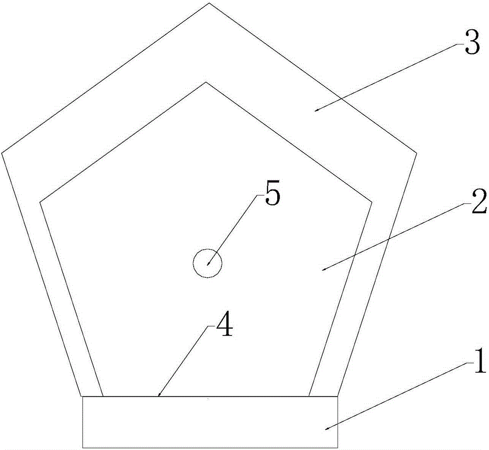
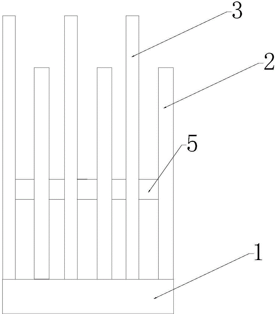
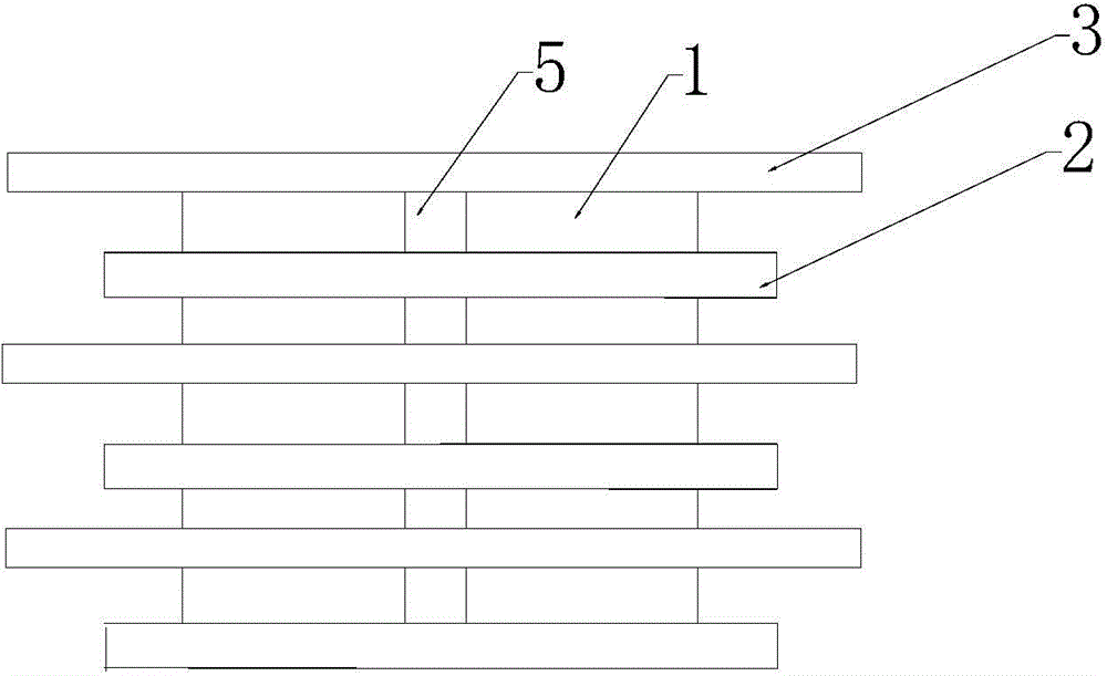
[0026] Such as Figure 1-Figure 3 As shown, it is a front view, a left view and a top view of the heat dissipation structure provided by Embodiment 1 of the present invention.

[0027] A uniform heat dissipation structure, including a heat sink 1 and a heat sink, the heat sink is vertically connected to the heat sink 1, and the heat sinks are distributed in parallel and kept at a certain distance, and the heat sink is divided into a first heat sink 2 and a second heat sink Two cooling fins 3, the shape of the first cooling fin 2 and the second cooling fin 3 is a regular pentagon, the side lengths of the first cooling fin 2 and the second cooling fin 3 are different, and the first cooling fin 2 and the second cooling fin 3 have different side lengths. The fins 2 and the second fins 3 are arranged at intervals on the heat sink 1, the fins are provided with through holes, the through holes on the first fin 2 and the through holes on the second fin 3 are located On the same axis,...

Embodiment 2

[0038] Such as Figure 4 As shown, in this embodiment, more than two first heat sinks 2 are arranged between two adjacent second heat sinks 3 , which provides more heat dissipation space for the second heat sink 3 .

Embodiment 3

[0040] Such as Figure 5 As shown, in this embodiment, more than two second heat sinks 3 are arranged between two adjacent first heat sinks 2. Generally speaking, the number of second heat sinks 3 is relatively large. The heat dissipation area of ​​the heat dissipation structure itself is improved.


PUM


Abstract

The invention relates to the technical field of heat radiators, in particular to a uniform heat radiation structure. The uniform heat radiation structure comprises a heat radiation seat and heat radiation fins perpendicularly connected with the heat radiation seat, wherein the heat radiation fins are distributed in parallel and at intervals and include the first heat radiation fins and the second heat radiation fins; the first heat radiation fins and the second heat radiation fins are in a regular pentagon shape, have different side lengths, are arranged on the heat radiation seat at intervals and are provided with through holes; the through holes in the first heat radiation fins and the through holes in the second heat radiation fins are located on the same axis; heat radiation pipes used for enabling the heat radiation fins to be communicated are arranged in the through holes, and the heat radiation pipes are tightly connected with the through holes. The heat radiation fins in the regular pentagon shape are adopted, are different in size and are arranged on the heat radiation seat at intervals, so that a larger heat radiation space is provided for every two adjacent heat radiation fins. All the heat radiation fins are communicated through the heat radiation pipes, so that the heat radiation structure is uniform in heat radiation, and the heat radiation efficiency is improved.

Description

technical field [0001] The invention relates to the technical field of radiators, in particular to a uniform heat dissipation structure. Background technique [0002] As we all know, too high temperature will cause certain damage to most non-high temperature equipment, such as LED, solar battery or computer CPU, etc., because the temperature itself will rise during operation, if it is not dissipated in time and effectively, it will lighten to a certain extent The efficiency will drop, and the equipment will burn out. In this case, radiators are often used as auxiliary equipment to dissipate heat. Radiators are generally composed of heat dissipation structures and other auxiliary structures. In the prior art, heat sinks in heat dissipation structures are mostly rectangular. Moreover, the size of each heat sink is the same, and the space is not well utilized, resulting in a small heat dissipation area of ​​the heat sink and low heat dissipation efficiency. When the heat sink a...

Claims


Application Information

Patent Timeline
Patent Type & Authority Applications(China)
IPC IPC(8): F28F7/00
Inventor 张芳芳
Owner WUXI JIAMEIDA RUBBER & PLASTIC EQUIP
Why Eureka
Try Eureka