Heat exchanger with corrugated pipe coil structure provided with internal duct and external duct

A technology of heat exchanger and bellows, which is applied in the field of heat exchangers, can solve the problems of no active air flow rate, large space occupation, and low heat exchange efficiency, and achieve integrated modularization, easy installation and portability, and heat exchange high efficiency effect

Inactive Publication Date: 2010-01-06
南京容宇能源科技有限公司
View PDF3 Cites 18 Cited by
  • Summary
  • Abstract
  • Description
  • Claims
  • Application Information

AI Technical Summary

Problems solved by technology

[0002] At present, most heat exchangers use finned heat sinks, and the arrangement of finned heat sinks is mostly parallel. Slow, long pipeline, small bending radius, large fluid resistance, easy to leak, complicated manufacturing process, high manufacturing cost, such as disclosed heat exchangers such as CN2463756Y
CN2752664Y discloses a radiator with a metal coil structure with internal and external threads. The coil structure is "mouth" or "L". Stainless steel pipes / threaded pipes are assembled with heat dissipation fins, but whether it is a coil structure heat exchanger or a traditional heat exchanger with finned radiators, when used in some closed equipment or places, where There is no active air velocity in the space (such as the chassis, etc.), the heat exchange efficiency is low, and if there are temperature-sensitive components in the space (such as the chassis), it is easy to cause failure
[0003] In addition, the above-mentioned structure is usually not corrosion-resistant. In order to prevent corrosion, the above-mentioned types of heat exchangers are mostly assembled with stainless steel pipes with cooling fins, or with anti-corrosion inner tubes, which affects the heat dissipation efficiency and requires die-casting technology. , high manufacturing cost

Method used


Image

  • Heat exchanger with corrugated pipe coil structure provided with internal duct and external duct
  • Heat exchanger with corrugated pipe coil structure provided with internal duct and external duct

Examples


Embodiment 1

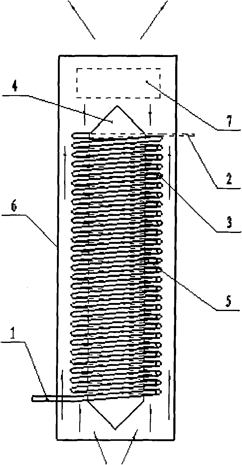
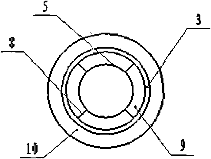
[0022] Embodiment 1: Taking the heat exchanger described in the present invention as an example for the heat dissipation of the electrolyte in the hydrogen-oxygen generator, the structure of the heat exchanger described in this embodiment is as attached figure 1 And attached figure 2 As shown, a heat exchanger with a corrugated coil structure with internal and external ducts consists of an inlet 1, an outlet 2, a bellows 3, a fairing 4, an inner ring sleeve 5, an outer ring sleeve 6, a fan 7, and a bracket 8 composition.

[0023] The bracket 8 is a group of raised brackets fixed on the outer wall of the inner ring sleeve 5 for fixing the bellows 3 to form a coil structure (see attached figure 2 ). The bellows 3 spirally surrounds the outer wall of the inner ring sleeve 5 through the bracket 8 (see attached figure 1 ), the inner ring duct 9 is formed between the outer wall of the inner ring sleeve 5 and the bellows 3, the bellows 3, the fairing 4, the inner ring sleeve 5, ...

Embodiment 2

[0034] Embodiment 2: Taking the heat exchanger of the present invention used in air-conditioning equipment as an example, the structure of the heat exchanger is the same as in Embodiment 1, the inner walls of the inlet 1 and outlet 2 are made of stainless steel, and the material of the bellows 3 is stainless steel. When the refrigerant (such as Freon, etc.) flows into the bellows 3 in the heat exchanger from the inlet 1, a turbulent flow is formed in the tube wall with a corrugated structure, and the air in the inner and outer ducts outside the bellows passes through the bellows wall and the bellows. For heat exchange, the fan 7 discharges the cooled air in the inner and outer ducts, and the refrigerant flows through the bellows 3 in a spiral manner and then is discharged from the outlet 2 to achieve the purpose of cooling the air. At this time, it flows through the outlet 2 The temperature of the refrigerant is higher than the temperature at the inlet 1.


PUM


Abstract

The invention discloses a heat exchanger with a corrugated pipe coil structure provided with an internal duct and an external duct, which comprises an inlet, an outlet, a corrugated pipe, a dome, an internal ring bushing, an external ring bushing, a fan and a bracket. When fluid media to be in heat exchange flow in the corrugated pipe in the heat exchanger from the inlet, form a turbulent flow in a pipe wall with a corrugated structure and carry out heat exchange with air in the internal duct and the external duct outside the corrugated pipe via the wall of the corrugated pipe, the fan discharges air in the internal duct and the external duct, and the fluid media are discharged from the outlet after the heat exchange performed in the corrugated pipe in a spiral way. The heat exchanger has the advantages of high heat exchanger effectiveness, simple structural technology, light weight, integration, and the like, and the fluid media in the pipe coil after the heat exchange have even temperature, thereby the heat exchanger can be used for heat exchange of air, liquid and air-liquid mixing substances. When the corrugated pipe adopts resistant materials, the heat exchanger can be used for heat exchange for corrosive liquid media.

Description

technical field [0001] The invention relates to a heat exchanger, which is especially suitable for heat dissipation or refrigeration of liquid, gas, and gas-liquid mixture, and can be used in chemical industry, construction and other fields. Background technique [0002] At present, most heat exchangers use finned heat sinks, and the arrangement of finned heat sinks is mostly parallel. Slow, the pipeline is long, the bending radius is small, the fluid resistance is large, easy to leak, the manufacturing process is complicated, and the manufacturing cost is higher, such as disclosed heat exchangers such as CN2463756Y. CN2752664Y discloses a radiator with a metal coil structure with internal and external threads. The coil structure is "mouth" or "L". Stainless steel pipes / threaded pipes are assembled with heat dissipation fins, but whether it is a coil structure heat exchanger or a traditional heat exchanger with finned radiators, when used in some closed equipment or places,...

Claims


Application Information

Patent Timeline
Patent Type & Authority Applications(China)
IPC IPC(8): F28D7/10F28F9/22F25B39/02C25B1/02
CPCY02P20/10
Inventor 吕新民杜海涛陈姚建平
Owner 南京容宇能源科技有限公司
Why Eureka
Try Eureka