

Railway wagon brake beam fatigue test bench guide sleeve clearance elimination device
A fatigue test, railway wagon technology, applied in railway vehicle testing, etc., can solve problems such as unreliability, constraints, test loading frequency drop, etc., to achieve the effect of ensuring accuracy, ensuring test efficiency, and avoiding the reduction of loading frequency
- Summary
- Abstract
- Description
- Claims
- Application Information
AI Technical Summary
Problems solved by technology
Method used
Image

Examples
Embodiment 1
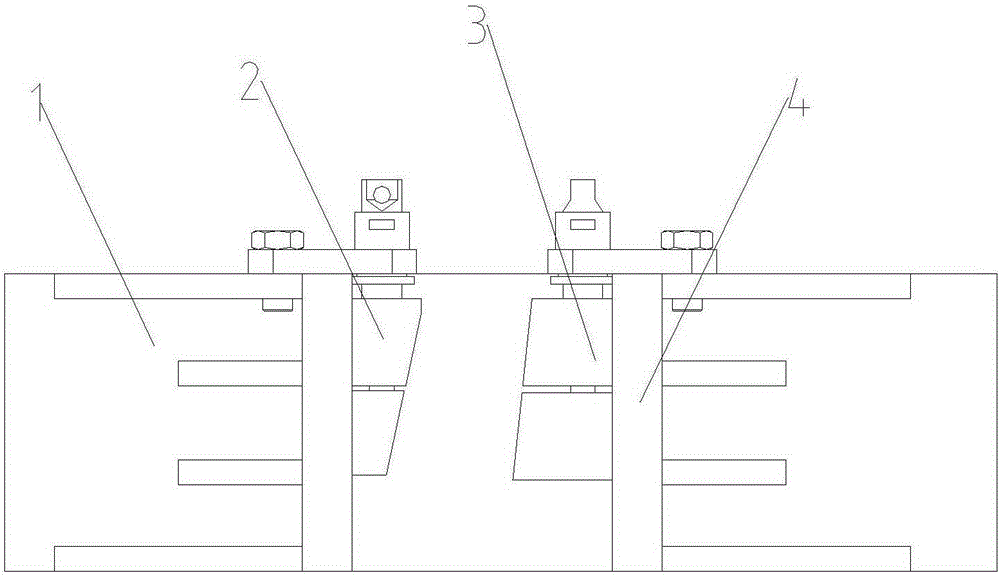
[0028] Such as figure 1 As shown, the guide sleeve gap elimination device of the railway wagon brake beam fatigue test bench includes the adjustment device I2 and the adjustment device II3 used in pairs. During the test, the two are respectively installed on the test bench 1, and the left and right sides of the brake beam guide sleeve sides.
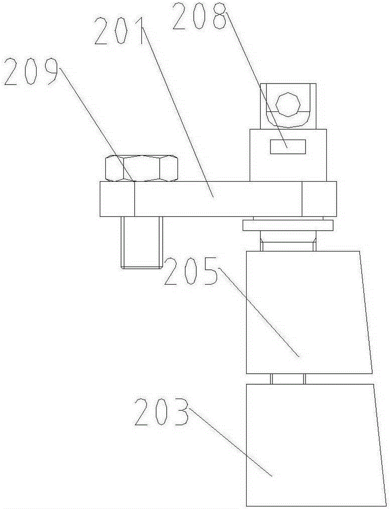
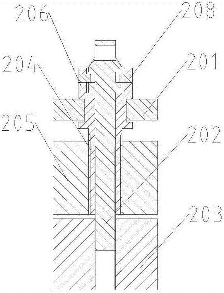
[0029] Such as figure 2 and image 3 As shown, the adjustment device I2 includes a pressure plate 201, an inner adjustment shaft 202 and a lower adjustment block 203; the lower adjustment block 203 is installed on the inner adjustment shaft 202, and the two are screwed together, and the lower adjustment block 203 can be adjusted by rotating the inner adjustment shaft 202. Up and down positions; the side of the lower adjustment block 203 facing the guide sleeve is an inclined surface, and the inclined surface is attached to the outer wall of the guide sleeve.
[0030] In addition to the inner adjustment shaft 202 and the lower adjustm...
Embodiment 2
[0037] Embodiment 1 is the best embodiment of the present invention. In application, in order to simplify the structure and volume of the clearance eliminating device, the upper adjustment block 205 and the outer adjustment shaft 204 can be omitted, and only the lower adjustment block 203 and the inner adjustment shaft 202 remain.
[0038] In this embodiment, the specific structure of the gap eliminating device is as follows:
[0039] Such as Figure 8 As shown, the adjustment device I2 includes a pressure plate 201, an inner adjustment shaft 202 and a lower adjustment block 203; the lower adjustment block 203 is installed on the inner adjustment shaft 202, and the two are screwed together, and the lower adjustment block 203 can be adjusted by rotating the inner adjustment shaft 202. The upper and lower positions; the pressure plate 201 has a shaft groove 204, and the inner adjustment shaft passes through the shaft groove 204; the side of the lower adjustment block 203 facing...
PUM
 Abstract
Description
Claims
Application Information