Novel down lead wire clamp

A down conductor clip and a new type of technology are applied in the field of improvement of down conductor clips for overhead optical cables, which can solve the problems of reduced installation quality, small contact area, deformation of openings, etc., and achieve improved reliability, good adaptability, and easy selection. Effect

Inactive Publication Date: 2016-01-06
江苏英华电力成套设备有限公司
View PDF0 Cites 0 Cited by
  • Summary
  • Abstract
  • Description
  • Claims
  • Application Information

AI Technical Summary

Problems solved by technology

[0004] Its disadvantages are: (1) The "U"-shaped clip bites one side of the tower material through 1-2 bolts, and the part that engages with the tower is one end of the bolt, the contact area with the tower is very small, and the reliability is poor; (2 ) Due to the aforementioned installation method, if the installer tightens the bolts too tightly, the opening of the "U" clamp will be deformed to a "V" shape, resulting in a decrease in installation quality

Method used


Image

  • Novel down lead wire clamp
  • Novel down lead wire clamp
  • Novel down lead wire clamp

Examples


Embodiment Construction

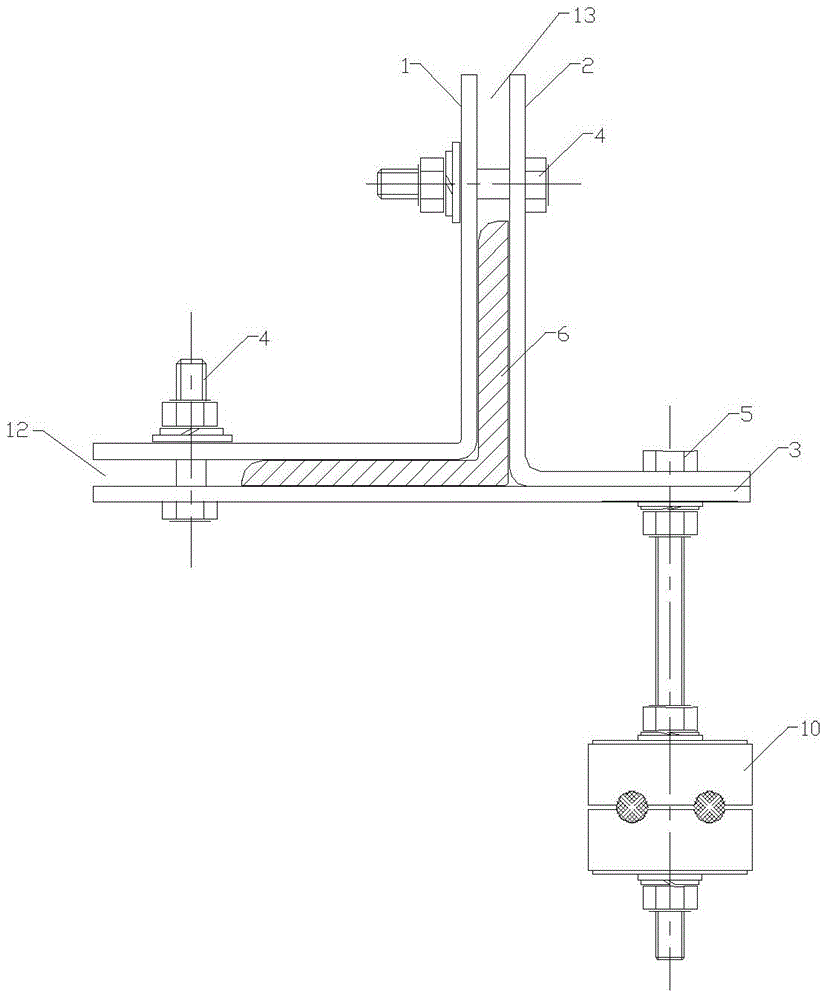
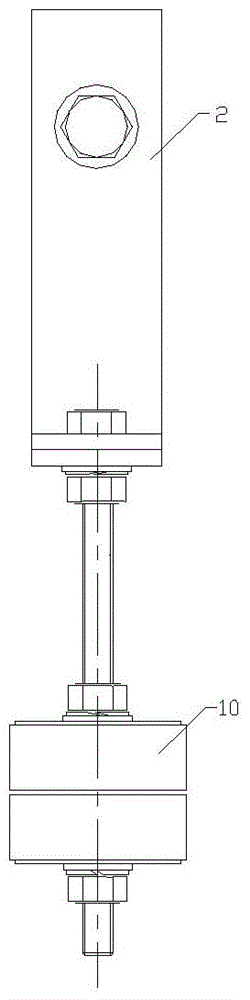
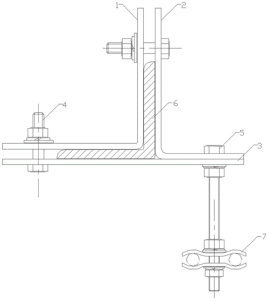
[0025] The invention is like Figure 1-6 As shown, it includes an installation splint and a cable clamp. The installation splint includes a left splint 1, a right splint 2 and a straight splint 3. The left splint 1 and the right splint 2 are L-shaped and have a horizontal plate and a vertical plate. , The straight splint 3 is plate-shaped;

[0026] The horizontal plates of the left splint 1 and the right splint 2 are respectively arranged outwards (toward the outside of the respective vertical plates) and are respectively parallel to the straight splint 3, and the horizontal plates of the left splint 1 are connected by fastening bolts 4 On the straight splint 3, the horizontal plate of the right splint 2 is connected to the straight splint 3 by a long bolt 5, and a horizontal accommodation space 12 is provided between the left splint 1 and the straight splint 3;

[0027] The vertical plates of the left splint 1 and the right splint 2 are parallel to each other and are connected by...


PUM


Abstract

The invention provides a novel down lead wire clamp which is simple and convenient in structure, high in reliability and convenient to install. The novel down lead wire clamp comprises mounting clamping plates and a cable clamp, and is characterized in that the mounting clamping plates comprise a left clamping plate, a right clamping plate and a straight clamping plate, the left clamping plate and the right clamping plate are L-shaped and are respectively provided with a horizontal plate and a vertical plate, and the straight clamping plate is in the shape of a flat plate; and horizontal plates of the left clamping plate and the right clamping plate are arranged outward and respectively parallel to the straight clamping plate, the horizontal plate of the left clamping plate is connected to the straight clamping plate through a fastening bolt, the horizontal plate of the right clamping plate is connected to the straight clamping plate through a long bolt, and a horizontal containing space is reserved between the left clamping plate and the straight clamping plate. The down lead wire clamp provided by the invention is more reasonable in structure, higher in reliability, better in adaptability, convenient to install and capable of being adjusted in size.

Description

Technical field [0001] The invention relates to the improvement of a down-lead clamp for overhead optical cables. Background technique [0002] When an overhead optical cable is erected on a communication line, due to the influence of factors such as the manufacture, transportation, construction, and traction of the optical cable, the optical cable connection device is indispensable. The optical cable is on the connecting tower, and the distance between the installation position of the optical cable and the installation position of the connecting box is often several meters or even hundreds of meters. Install one at 1-3 meters. [0003] Such as Figure 7 As shown, in the prior art, the component connecting the down-lead clamp and the L-shaped angle steel of the tower is a "U"-shaped clamp. When installed, the U-shaped clamp 11 is clamped on the angle steel, and one or two bolts bite the angle steel. One side of the L shape is fixed. [0004] Its disadvantages are: (1) The "U"-shape...

Claims


Application Information

Patent Timeline
IPC IPC(8): G02B6/48
Inventor 施国爱
Owner 江苏英华电力成套设备有限公司
Why Eureka
Try Eureka