Imaging lens system
An imaging lens and lens technology, applied in optical components, optics, instruments, etc., can solve the problems of increasing the total length of the lens system, unable to fully correct aberrations, etc., and achieve the effect of small and light structure and excellent optical performance.
- Summary
- Abstract
- Description
- Claims
- Application Information
AI Technical Summary
Problems solved by technology
Method used
Image
Examples
no. 1 example
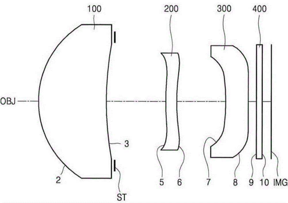
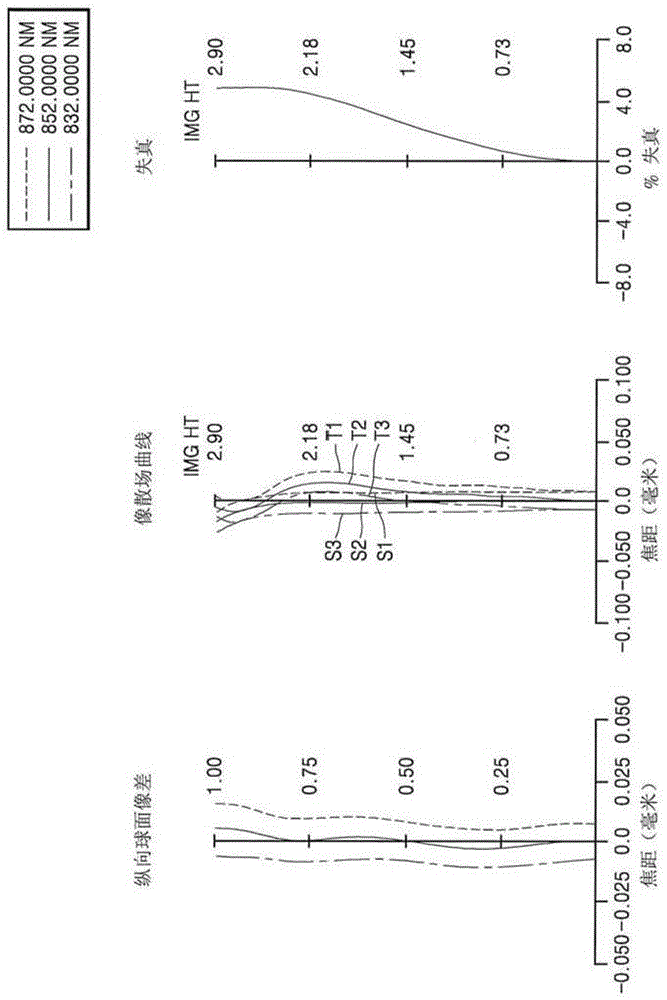
[0080] figure 1 The optical arrangement of the imaging lens system according to the first embodiment of the present invention is shown, and the lens data of the first embodiment are as follows.
[0081] Table 1
[0082] Fno.=1.6, f=11.868
[0083] S
R
T
Nd
Vd
OBJ
No tamp
0.0000
2*
4.4254
3.4516
1.5238
55.7283
3*
22.6280
0.4278
ST
No tamp
2.6240
5*
23.9624
0.5500
1.5238
55.7283
6*
10.8748
2.5357
7*
-9.9690
1.1368
1.5238
55.7283
8*
282.0169
0.4000
[0084] 9
gigantic
0.3000
64.1664
10
gigantic
0.4742
gigantic
0.0000
[0085] The aspheric coefficients are as follows.
[0086] Table 2
[0087] S
2
3
5
6
7
...
no. 2 example
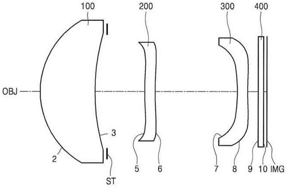
[0091] image 3 The optical arrangement of the imaging lens system according to the second embodiment of the present invention is shown, and the lens data of the second embodiment are as follows.
[0092] table 3
[0093] Fno.=1.6838, f=11.911
[0094] S
R
T
Nd
Vd
OBJ
gigantic
0.0000
2*
4.3034
2.8733
1.5238
55.7283
3*
13.0828
0.6226
ST
gigantic
2.0216
5*
28.3459
0.5500
1.5238
55.7283
6*
23.2018
4.3485
7*
-19.1535
0.5555
1.5238
55.7283
8*
14.1682
0.5621
9
gigantic
0.3000
64.1664
10
gigantic
0.1663
gigantic
0.0000
[0095] The aspheric coefficients are as follows.
[0096] Table 4
[0097]
[0098]
[0099] Figure 4 The longitudinal sp...
no. 3 example >
[0102] Figure 5 The optical arrangement of the imaging lens system according to the third embodiment of the present invention is shown, and the lens data of the third embodiment are as follows.
[0103] table 5
[0104] Fno.=1.5841, f=11.949
[0105] S
R
T
Nd
Vd
OBJ
gigantic
0.0000
2*
4.3830
3.4816
1.5238
55.7283
3*
15.9142
0.5516
ST
gigantic
2.0113
5*
27.3688
0.5500
1.5238
55.7283
6*
19.5099
3.4163
7*
-6.3764
0.8891
1.5238
55.7283
8*
-33.4093
0.4064
9
gigantic
0.3000
64.1664
10
gigantic
0.3935
[0106] IMG
gigantic
0.0000
[0107] The aspheric coefficients are as follows.
[0108] Table 6
[0109] S
2
3
5
6 ...
PUM
 Abstract
Description
Claims
Application Information
 - R&D
- Intellectual Property
- Life Sciences
- Materials
- Tech Scout
- Unparalleled Data Quality
- Higher Quality Content
- 60% Fewer Hallucinations
Browse by: Latest US Patents, China's latest patents, Technical Efficacy Thesaurus, Application Domain, Technology Topic, Popular Technical Reports.
© 2025 PatSnap. All rights reserved.Legal|Privacy policy|Modern Slavery Act Transparency Statement|Sitemap|About US| Contact US: help@patsnap.com


